Frequently asked questions and answers for Level Switches - Industrial Automation
Question
Is it possible to use a commercially available terminal block or to make one yourself, instead of using the one that comes with K7L Liquid Leakage Sensors?
Answer
Yes, either of these can be used. However, when using a different terminal block, make sure that proper insulation is provided between the terminals, and that there is no danger of a ground fault in the cables or Liquid Leakage Sensing Bands.
Note:For explosion-proof areas, use F03-20 Liquid Leakage Sensor, which has been certified for intrinsic safety and explosion-proof capability.
Question
How long is your longest Liquid Leakage Sensing Band? Also, how do you join two Bands together?
Answer
1. The maximum length is 100 m.
The possible lengths of sensor cable for a Water Leak Detector (61F-GPN-V50, 61F-WLA) for different lengths of Sensing Bands (F03-15, -16PE, -16PT) are shown below, where the reset current is set at a minimum of 0.15 mA. When the leakage current of the sensing band set to more than 0.15 mA, the water leak detector cannot reset. When the leakage current of the Sensing Band is less than 0.15 mA, the corresponding cable length is okay.
Possible Length of Sensor Cable (Sensing Band + IV Cable)
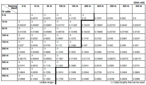
Note:IV cable (2 mm2), Sensing Band (F03-15, F03-16PE)
2. The sensing bands can be joined together with the following steps.
Connecting Water Leak Detector Sensing Bands
F03-15 Sensing Band
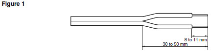
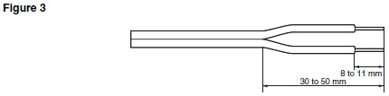
(1)Connecting the Sensing Band Directly to the Water Leak Detector Strip away about 8 to 10 mm of the sheath from the end of the sensing band.
(2)Connecting the Sensing Bands Together
Connect the sensing bands using an insulated crimp sleeve or a closed end connector. Install a pull box (e.g., plastic) and keep the connected section inside it to keep it well insulated. If a pulling box cannot be installed, wrap some insulation tape around the connected section to keep it well insulated. When using a closed end connector, select cables that are similar in size and stiffness to the sensing cable. If a dissimilar cable must be connected, twist the more flexible cable around the stiff cable and use the closed end connector as a standoff connector. If required, remove any electrodes that are attached in close proximity to the connected section.
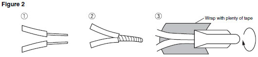
After putting the closed end connector over the joined section, pull the cable and wrap insulation tape around it.
Note:Use AMP Closed end connector, product number 35653 or equivalent.
F03-16PE Sensing Band
A standard F03-16PE sensing band is made from 0.3 x 1.5 rectangular lines.
(1)Connecting the Sensing Band Directly to the Water Leak Detector
Strip away about 8 to 10 mm of the sheath from the end of the sensing band and then connect it.
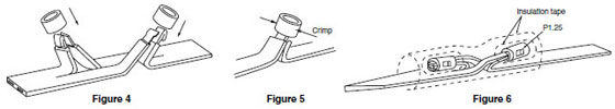
(2)Connecting the Sensing Bands Together (Using Crimp Sleeve P-1.25 or B-1.25)
Note:P-1.25 and B-1.25 are JIS titles for general electrical wiring.
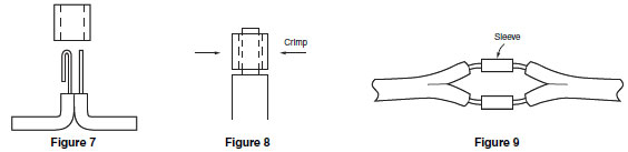
(a)Cut a slit in the center of the sensing band with a utility knife. Leave the insulation intact on the inside.
(b)Strip back the insulation so that the enough wire is exposed to fit into the sleeve in the configuration shown in Figure 7.
(c)Pull the sleeve over the wires and crimp in the directions shown in Figure 5 and Figure 8. Pull on the wire to check whether the crimping is effective.
(d)Wrap each connection with insulation tape, then bend the connected sections in opposite directions as shown in Figure 6. Wrap the whole section with insulation tape for protection (see Figure 6).
(3)The sensing bands can also be connected by inserting them from opposite ends of sleeve.
As shown in Figure 9, the sensing bands can be inserted from opposite ends of the crimp sleeve to meet in the middle. Either P-1.25 or B-1.25 crimp sleeves can be used but make sure that the crimped section is big enough to fit three folds of the cable conductors.
Crimp in the directions as shown in Figure 5 and Figure 8.
Wrap each connection with insulation tape, then wrap the whole section with insulation tape again for protection.
(4)Connecting the Sensing Band and Lead Wires
Connect the sensing band and lead wires using the method described in the previous item (3). Use a B-1.25 crimp sleeve. (Refer to Figure 9.)
Question
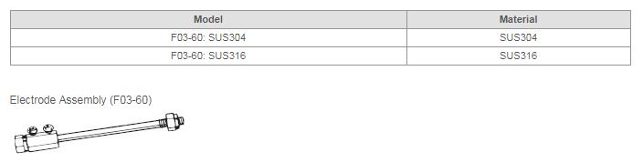
What all is included with an Electrode Assembly?
Answer
An Electrode Assembly includes an electrode, a connection nut, two lock nuts, and two spring washers.
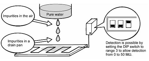
Can the Liquid Sensor "K7L" detect pure water?
AnswerYes, it can.
Even pure water with resistance of 10MΩcm or above includes lots of impurities when it leaks and then the resistance decreases. Thus, use the K7L with maximum sensitivity to detect almost all of impurities.
What should you do if you don't want to use the pump idling prevention function of 61F-G1N/-G1 Floatless Level Controllers?
Interconnect the E1' and E3 terminals on the Controller.
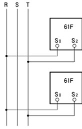
Which Controller model is best for simple liquid-level detection without pump control?
61F-GP-N Floatless Level Controller is suitable.
Prepare the same number of 61F-GP-N Controllers as the number of liquid-level detection points.
Note:The power supply phases (terminals 3 to 9) can be matched to use the same ground for the common Electrode (the longest Electrode, terminal 4).
It seems that 61F's Floatless Level Controller electrodes are dirty and sensitivity has dropped. How can I clean them?
Tarnish on the electrodes will cause poor conductivity.
Polish the electrodes with an abrasive such as fine sandpaper.
Use a cloth to wipe off the residue.
The electrodes are stainless steel, so it is also acceptable to use a commercial chemical cleanser, but be sure that the liquid in the container is not affected. If the electrodes are extremely dirty, it may be necessary to replace them.
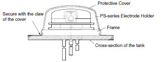
Is there a protective cover available for using PS-3S Electrode Holder outdoors?
Use F03-11 Protective Covers.
The Protective Cover can be mounted only by using F03-12 Frames (sold separately) as a flange, or by using F03-12 and F03-13 Frames (both sold separately) together and embedding them in a concrete tank.
Attach F03-12 Frames to the bottom of PS-series Electrode Holders. (See figure below.) Next, place F03-11 Protective Covers on top of the Electrode Holders and press on it until it clicks into place.
Note:The cap screw attached to the Protective Covers are not required for mounting.
Remove the two mounting screws (M5 x 25) of BF-series Electrode Holders and attach the two cap screws (M5 x 25) provided with F03-11 Protective Covers.
Next, put Protective Covers over the top of BF-series Electrode Holders, and then tighten the two enclosed screws (M3 x 20 with washers). See figure below.
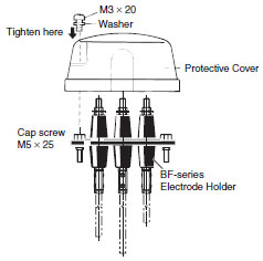
Note:Protective Covers cannot be mounted on BF-1.
Can K7L Liquid Leakage Sensor be used as a substitute for 61F-GPN-V50 Water Leak Detector?
Yes, it can be used, but it has different surge resistance characteristics, so do not use it in locations where it may be subjected to impulse surges, such as an outdoor rooftop or pump panel.
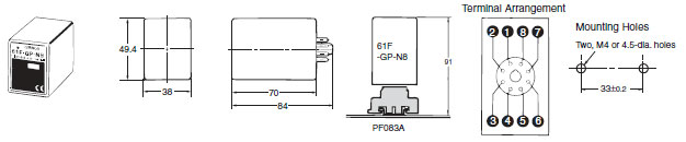
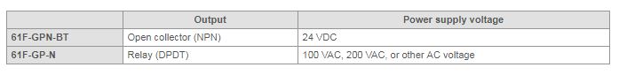
What's the difference between 61F-GP-N8H and 61F-GP-N8HY Floatless Level Controllers?
61F-GP-N8H is a high-sensitivity, advanced-operation Controller.
61F-GP-N8HY is a high-sensitivity, sequential-operation Controller.
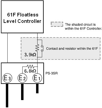
What is the two-wire operating principle of 61F-[]R Floatless Level Controller?
The wiring for the self-holding circuit is eliminated in order to eliminate one wire between the 61F and the electrodes. (The electrode itself is not eliminated.)
1.Even though a Controller is called a Two-wire Controller (such as the 5-wire 61F-G3N becoming a 4-wire 61F-G3NR), the actual wiring is not necessarily limited to just two wires.
2.A Two-wire Electrode Holder (with a model number ending in R) is required for a two-wire circuit.
Two resistors are connected in series: a 6.8 kΩ resistor in the Electrode Holder and 3.9 kΩ resistor in the 61F Controller.
Even if the rising water submerges E2, the resistance will be 6.8 kΩ + 3.9 kΩ = 10.7 kΩ, so the Controller's circuit will not operate. If the water reaches E1, the resistance will be only 3.9 kΩ, so the Controller's circuit will operate and the internal relay contacts will switch. When the water level falls below E1, there is still a resistance of 6.8 kΩ from E2 at the Controller's contact, so the relay is held.
How does the Floatless Level Controllers "61F"operate when the power returns after power failure?
f the power fails while the self-holding circuit is set to ON, the self-holding circuit is turned OFF and kept in the OFF state even after the power recovers. Therefore, when using the Floatless Level Controller "61F-GN", in the automatic operation of water supply, the pump is ON until the level of water reaches the Electrode "E1".
Meanwhile, in the automatic operation of water drainage, the pump is not turned ON until the level of water reaches the E1.
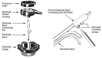
How do you mount F03-05 Electrode Band?
Screw the Electrode Band connecting nut into to the electrode nut inside the electrode section and secure with the clamp screws. Insert the Electrode Band into the lower hold of the connecting nut, and tighten the two clamp screws so that the conductor in the Electrode Band will come into contact with the connecting nut. Then mount the Electrode Holder to the electrode section and secure them with two mounting screws, and put the drip-proof cover on top.
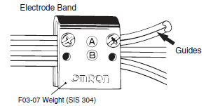
Mounting Weight (1)
To mount an Electrode Band Weight on an Electrode Band, firmly tighten the two screws A or B. The needle screws will come into contact with the electrode wire conductor) allowing the Electrode Band Weight to become an electrode plate. (Be sure to use screw holes A or B.)
The Electrode has guides for connecting screws as shown by the arrows below so that connecting screws can be properly inserted into the conductor.
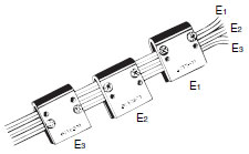
Mounting Weight (2)
Install Electrode Band Weights in three positions at different heights. The Electrode Band Weights work on the E1, E2, and E3 electrodes, allowing the Electrode Band to detect high, medium, and low levels of liquid.
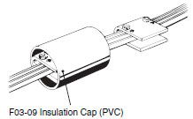
Cover each Electrode Band Weight with an Insulation Cap so as to prevent false detection due to contact between the electrode and tank. Deform the Insulation Cap to an ellipsoid before installing it on the Electrode Band Weight.
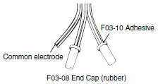
Cover the Electrode Band end and apply F03-10 Adhesives sold separately to prevent water from entering between the sheath and the End Cap.
Five end caps can be glued with one Adhesive.
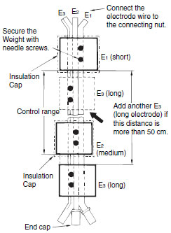
If the distance between the long electrode (E3) and short electrode (E1) in purified city water is more than 50 cm, install other Electrode Band Weights as E3 in the vicinity of E1 at intervals of 15 to 20 cm, referring to Mounting Weight (2) above. An Insulation Cap is not needed for the long electrode.
What would be an appropriate 61F Floatless Level Controllers, Electrode Holders, and Electrodes for detecting the level of seawater?
Use a low-sensitivity 61F (one with the suffix D on the model number), BS-1T Electrode Holders (titanium), and F03-01 Electrodes (titanium).
If BS-1 or BF-1 Electrode Holders is used, the stainless-steel electrode nuts will corrode and have to be regularly replaced.
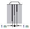
Also, allow at least 1 m of space between Electrodes.
Are there any precautions for the mounting interval, separators, taping, and wavebreaking pipes when mounting Electrodes?
Note the following Electrode precautions.
1.When cutting an Electrode, be sure to chamfer cut surfaces of the electrode.
2.Maintain a Clearance Between Electrodes
Maintain sufficient clearance (normally 1 m) between Electrodes in sea water or contaminated water. Use 61F-[]D (or -[]ND) low sensitivity models if this clearance is difficult to maintain.
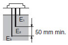
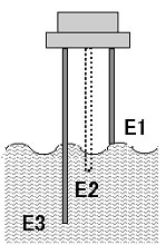
3.Long Ground Electrode
The Electrodes are mounted in sets of three. Connect the shortest Electrode to E1, the medium Electrode to E2 and the longest Electrode to E3. The longest Electrode, E3, must be at least 50 mm longer than the other Electrodes.
4.Consider the Operating Level
Due to the liquid type and fluctuations in the power supply voltage, the operating level may fluctuate to a small degree from the level at which the liquid surface makes contact with the Electrode tip.
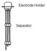
5.Use Separators If the Electrode length reaches 1 m min., insert Separators at the joint positions to prevent the Electrodes touching each other in the liquid.
6.Do Not Allow Suspended Matter to Short the Electrodes
If suspended matter may short the electrodes, use tubing electrodes. The tubing must be removed at least 100 mm from the bottom end to ensure sufficient conductivity. Do not use a tubing electrode as a ground electrode.
7.Mount Electrodes Vertically
Install the Electrodes vertically to avoid the accumulation of slime which can form an insulating layer on the Electrode surface.
8.Keep Electrodes Clean
Lift the Electrodes and remove the surface film with fine sandpaper about 6 months after installation. Subsequently, repeat this cleaning once or twice per year.
Cleaning is particularly important for Electrodes used in a liquid containing large amounts of dirt or slime, which can build up into an insulating film on the Electrode surface and cause malfunctions. Clean the surface insulating film from Electrodes used in this environment once every three months. Use a pipe, as shown in the diagram below in situations where the water contains large amounts of dirt.
Use a pipe as shown to keep dirt and oil films from the Electrode in situations where the liquid is highly contaminated with dirt and oil, such as sewage holding tanks.
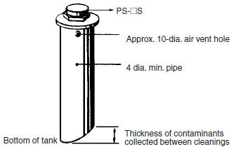
Use a pipe at least 4 inches in diameter.
Cut off the end of the pipe at an angle to clear the estimated amount of contaminants accumulating at the bottom of the tank.
Drill an approximately 10-dia. vent hole at the top of the pipe.
Using an Anti-ripple Pipe:
Use an anti-ripple pipe as shown below in cases where large ripples are produced by a rapid fluid flow rate.
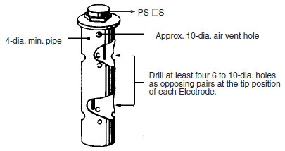
Use a pipe at least 4 inches in diameter.
To improve liquid circulation inside the pipe, drill at least four 6 to 10-dia. holes as opposing pairs at the tip position of each Electrode.
Drill an approximately 10-dia. vent hole at the top of the pipe.
Follow the information above with regard to using Electrodes.
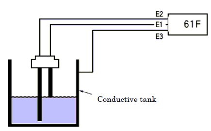
What is the voltage between electrodes of the Floatless Level Controllers "61F"?
Between the level electrode and the common electrode, when they do not soak in the liquid the voltage is about 7-8VAC. When they soak in the liquid the voltage decreases to about 0V according to the specific resistance of the liquid. Therefore, when the 61F is individually inspected, be sure to measure the voltage between their terminals by leaving the electrodes open.
In the case of a high-sensitivity model, that with 24VAC is also available.
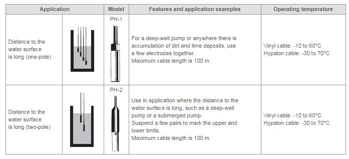
What is the difference between PH-1 and PH-2 Underwater Electrodes?
PH-1 is a One-pole Electrode. PH-2 is a Two-pole Electrode, with a ground electrode and an operation electrode.
Use PH-1 for liquids that contain a large amount of foreign matter. Use PH-2 for liquids that do not contain a large amount of foreign matter because it is more convenient.
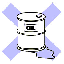
Can the Liquid Leakage Sensor Amplifiers "K7L" detect oil?
It is almost impossible.
However, in the case when oil such as cutting oil and used engine oil contains lots of impurities including metal powders, it may be detected.
Confirm the above by evaluating with actual equipment.
Are there any points to look out for when changing over from 61F-APN Alternate Operation Relays to 61F-APN2?
61F-APN and 61F-APN2 differ in outer dimensions, so the compatible Sockets and the mounting method will be different. This means that the Sockets must also be replaced, and the terminal arrangement will be reversed, so the wiring will have to be changed as well.
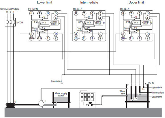
Can two 61F Floatless Level Controllers and two Electrode Holders be used in the same tank?
Yes, they can as long as the following conditions are met.
Are Photoelectric Sensors that can be used in water available?
There are three types: F03-14 1P, F03-14 3P, and F03-14 5P.
They are mounted to the coupling part of 1-m Electrodes.
F03-14 1P is a one-pole type and there are no restrictions on its mounting intervals, so any Electrode Holder can be used.
F03-14 3P and F03-14 5P can be used only with PS-[]S Electrode Holders.
Are there any points to look out for when changing over from discontinued 61F-GP Floatless Level Controllers to substitute 61F-GP-N8?
61F-GP-N8 and 61F-GP differ in outer dimensions so the compatible Sockets and the mounting method will be different. This means that the Sockets must also be replaced, and the terminal arrangement will be reversed, so the wiring will have to be changed as well.
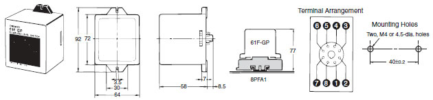
The substitute 61F-GP-N8 can also be inserted into an existing 8PFA1 Sockets (with no wiring change necessary). However, when this done, the placement of 61F-GP-N8 itself becomes vertically reversed. 61F-GP-N8 will operate normally in this condition, but the Holders cannot be mounted to it. This means that it will have no protection against vibration.
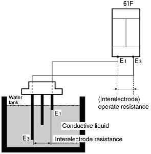
What is interelectrode resistance of 61F Floatless Level Controller?
The interelectrode resistance is basically the same as the operate resistance. The operate resistance includes the wiring from the 61F Controller's inputs (electrodes) to the 61F Controller, so the two values are not necessarily the same when there is a long distance, but generally they can be treated as the same value without any problems.
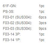
How is the electrode or electrode band mounted to the PS-[]S Electrode Holder, and what parts are required?
Number of Parts Required During Installation (Bar Electrode)
Automatic Water Supply or Drainage Control (Example)
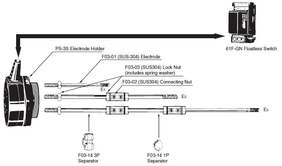
Number of Parts Required When E1 = 1 m, E2 = 2 m, and E3 = 3 m:
Number of Parts Required During Installation (Electrode Band)
Automatic Water Supply or Drainage Control (Example)
Number of Parts Required for a 3-m Electrode Band:
Is it a problem if Electrode terminals are interconnected during use?
There is no problem if Electrode terminals are interconnected. (They can be interconnected either when testing or using 61F Floatless Level Controllers.)
Because of the impedance in the relays that lay between the Electrodes of 61F, less than 2 mA flows between General-purpose Electrodes when the terminals are interconnected. The current that flows between High-sensitivity and Ultra High-sensitivity Electrodes is in the order of microamps.
When interconnecting Electrode terminals of 61F with switches, be sure to use Basic Switches.
Are there any precautions to observe when controlling pure water with 61F Floatless Level Controller?
The conductivity or specific resistance is a factor in the selection of a 61F Controller. Measure the interelectrode resistance to select the proper model accurately. A 61F Controller can be used if the measured value is within the "interelectrode operate resistance" listed in the Specifications Table of the Datasheets (F030-E1-09).
When the resistance range is measured with an instrument such as a multimeter, the interelectrode resistance cannot be measured accurately because the electrode voltage is DC. Always use the 61F Controller's interelectrode voltage (AC) to measure the interelectrode resistance.
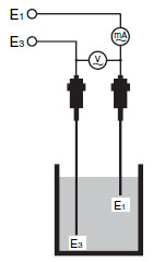
Measuring the Interelectrode Resistance
When the Controller is not operating properly even though it is wired properly, measure the interelectrode resistance. In this case, use a voltmeter and ammeter to measure the voltage drop, as shown in the following diagram.
The interelectrode resistance (liquid resistance between E1 and E3) can be calculated with the following equation.
R = V⁄I
R: Liquid resistance between the electrodes (kΩ)
V: Voltmeter's displayed value (V)
I: Ammeter's displayed value (mA)
Select an appropriate 61F Controller model based on the value of R.
The following list can be used as a guide to select a 61F Controller model from the conductivity.
Operate resistance:
0.5 to 2 μS (microsiemens) → 61F-UHS (0 to 1 MΩ)
2 to 5 μS → 61F-GP-NH3 (0 to 200 kΩ)
5 to 10 μS → 61F-GH (0 to 70 kΩ)
61F-GP-NH (0 to 40 kΩ)
61F-GPN-V50 (0 to 50 kΩ)
15 to 25 μS → 0 to 4 kΩ for standard general-purpose applications
Note:
1.With the 61F-HSL Ultra High-sensitivity model, a DC current flows through the electrodes. If the electrodes are usually submerged, galvanic corrosion will occur, so the Ultra High-sensitivity model cannot be used for control. Applications are restricted to upper limit alarms and leakage detection (e.g., errors, external tank overflow detection, etc.)
2.For pure water over 1 MΩ(18 MΩ model also available), use K7L Liquid Leakage Sensor or E7A Level Switch or E7M Level Switch.
I'm using General-purpose 61F Floatless Level Controllers with cable conductor of 2 mm2 and a length that is less than 1 km, but it malfunctions. Is there a solution for this?
It's possible that the cable conductor diameter is too large. Try changing to 0.75-mm2 conductor, or replace 61F with a long-distance model.
*Stray capacitance increases with thick cable diameters, which shortens the applicable cable length.
Is it possible to cut Electrodes? Also, do you sell any long Electrodes?
Electrodes are sold in 1-m increments.
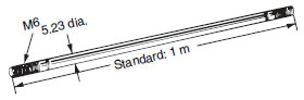
There are threads at both ends so it can be cut in half and used as two Electrodes. The threads (M6) have been created by rolling; you cannot cut a new thread.
When the required length of Electrode is more than 1 m, connect two Electrodes with a connecting nut and two lock nuts.
If the Electrodes are too long, it may cause problems with strength and handling. Cable-type Electrodes (PH) or Electrode Bands are more suitable.
Always use lock nuts so that Electrodes don't become loose.
Water inside the water tank may appear still even when it is actually flowing. This can cause considerable pressure on Electrodes, so make sure that they are secured properly. Also, sometimes the rods may bend from the force of the water. For applications involving tap water, use separators.
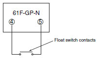
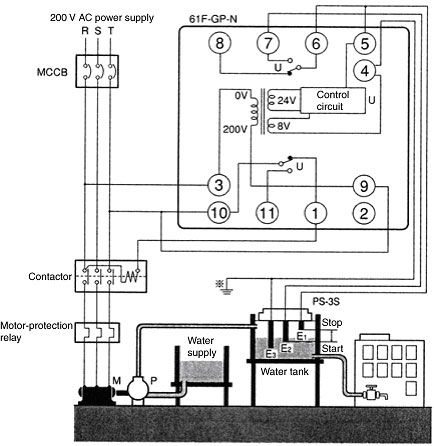
What kind of wiring is best to combine a 61F-GP-N Floatless Level Controller and float switch?
Connect the float switch's contact to pins 4 and 5 of the 61F-GP-N.
The voltage and current between the 61F electrodes is only about 8 VAC and 1 mA, so it is best to use a float switch contact that is for a minimal load.
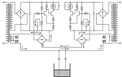
Is it possible to connect more than one 61F Floatless Level Controller to the same electrodes and share the electrodes?
Electrodes cannot be shared. Do not connect more than one 61F to the same electrode. If the voltage phases of the electrode circuits' 8-VAC power supplies are opposite, as shown in Figure 1, a closed loop circuit can pass through to two internal circuits (in the direction of the arrows) and the 61F can operate improperly when the power supply is turned ON, regardless of the water level.
Figure 2 shows how the power supplies' phases can be synchronized to prevent a loop circuit, but the 61F internal impedance will drop to approximately 1⁄2 of the correct impedance from the standpoint of the electrodes.
When using two or more 61F, separate the electrodes to prevent mutual interference. Sharing of the common electrode is acceptable.
Why doesn't the indicator light when I turn ON the power to 61F Floatless Level Controllers?
The indicator is an operation indicator, not a power indicator. It lights only when 61F is operating (when it is detecting the liquid surface).
When voltage is applied to 61F Floatless Level Controller, it operates regardless of the actual liquid level. What is the cause of the problem and how can it be corrected?
When the electrode cables are wired close to power cables or in the same duct, inductive noise from the power cables may cause the Controller to operate without any liquid.
Countermeasures:
Wire the electrode cables and power cables separately and avoid wiring closely. Also, properly ground the common voltage.
Countermeasures:
Separate the electrodes and install again.
Operation is not recovering due to a leakage current caused by parasitic capacitance to ground in the cables. The cables' surface area increases as the cable length increases and the parasitic capacitance to ground increases with more conductors, making it easier for poor recovery to occur.
Countermeasures:
Use a 61F Long-distance Controller.
Is it acceptable to wire 61F's Floatless Level Controller electrode cable and power cable in the same duct?
There is a possibility of improper operation, so avoid wiring the cables in the same duct or close together.
Since there is a weak current (about 1 mA at 8 VAC) between the 61F Controller and the electrodes, the electrode cables can be affected by inductive noise from the power cable and operate improperly. Also, be sure to check that the common electrode is grounded properly.
With 61F-G1 Floatless Level Controller, the water level of a water supply is above the E2' height, but the pump does not operate. What is the cause of the problem and how can it be corrected?
The following items may be the cause, so check these.
1.Momentarily short the E1' and E3 terminals of the 61F-G1 Controller to operate (self-hold) the U1 Relay Unit.
2.When the U1 Relay Unit will not operate (self-hold), replace the U1 Relay Unit. Also, check whether there is a damaged cable between the 61F Controller and electrode, and check whether the E2' electrode is coated with tarnish or oil.
3.As an emergency measure, operation can be forced by shorting the E1' and E3 terminals on the 61F-G1 Controller, however, idling cannot be prevented in this case.
The Floatless Level Controllers "61F" does not work even if it is powered on and the liquid level reaches the sensing level. What may be the reason for it?
Check the following points.
(1) Are there any problems with the wiring between the 61F unit and the electrode? (Are there any breaking, defective tightening or loosening of cables?)
(2) Is the type of liquid different from one that is used when the unit normally operates.
(3) Is an insulating film such as oil formed in the electrodes?
(4) Is a normal-sensitive model used for liquid with high specific resistance?
If the liquid's specific resistance is high, the unit may not operate in general sensitivity (0 to 4kΩoperate resistance). In this case, use a high-sensitive model with the model name ending in suffix H. Generally, a liquid contains less impurity, like distillated water and pure water, its specific resistance becomes higher. Oil cannot be used with the 61F.
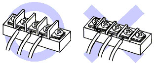
Can a single Liquid Leakage Sensor Amplifiers "K7L" detect more than one liquid leakage?
Yes, it can.
It is possible to detect more than one liquid leakage with a single K7L by connecting sensing bands in parallel with use of terminal blocks
However, be aware that the sensing band where a liquid is leaked cannot be specified.
Note: 1.
When wiring, be sure not to exceed the maximum possible wiring distances for both the connecting cable and the Sensing Band. Exceeding these distances may lead to faulty operation. Connect one Sensing Band to each Terminal Block.
Note: 2.
Not applicable to K7L-AT50D
Which 61F Floatless Level Controller is best to use for a Programmable Controller input? Pump control is being performed by the Programmable Controller.
We recommend the following models.
Why is the long common electrode always grounded in the 61F's Floatless Level Controller connection diagrams?
There are three reasons for this ground.
1.Preventing Improper Operation Due to Inductive Noise
Since there is just a weak current (about 1 mA at 8 VAC) between the 61F Controller and the electrodes, it is easy for inductive noise to cause improper operation when there is no ground.
2.Protecting the 61F Controller from Surge Voltage
The common electrode must be grounded properly to protect the 61F Controller's internal circuits from surges caused by lightning or other equipment.
3.Preventing Electric Shock
The ground is needed to prevent electric shock in case of electric leakage.
Can a 61F-GPN-V50 Water Leak Detector and Electrode be used as a set?
Yes, they can.
Use the same connections as the 61F-GP-N, shown in the following diagram.
Liquid level detection can be performed by leaving the E2 electrode unused and making no connections to terminals 6 and 7.
I want to use an iron tank without using a ground electrode of the Floatless Level Controllers "61F".
If the ground electrode line is connected to the tank, there is no problem.
In some cases, however, the tank has insulation coating on its internal walls, so make sure to check in advance that the system operates correctly.
However, do not use this method in the location where there is a noise source such as an inverter, because it may result in malfunctions.
Why do the specifications for the High-sensitivity 61F Floatless Level Controller say, "possible to use with 15 kOHM or less, however, this may cause reset failure"?
The interelectrode voltage of 61F is AC. This generates a floating capacitance between ground and the cable that connects the electrode bar to 61F body. The current that flows due to this cable-to-ground floating capacitance causes the reset failure.
The reset current for 61F High-sensitivity Controller is 0.05 mA AC min. If the current flowing through the ground capacity is, for example, 0.1 mA, there will be a reset failure because of the reset current (0.05 mA AC min.) even when there is no liquid between the electrodes.
In some cases, however, the tank has insulation coating on its internal walls, so make sure to check in advance that the system operates correctly.
However, do not use this method in the location where there is a noise source such as an inverter, because it may result in malfunctions.
Can PS-5S Electrode Holders be used to detect fluid level in warm (70 degree C) water?
No, PS-5S cannot be used for this. Steam would cause condensation to form inside PS-5S and result in insulation failure between its Electrodes.
In addition, the operating temperature range of the PS-5S is -10 to 70 degree C.
Depending on the amount of steam present, use either BF-5 or BF-1 Electrode Holders and allow some space between each Electrode.
BF-5 or BF-1 Electrode Holders can only be used, however, when there is no pressure applied. In other words, the operating pressure must be atmospheric pressure.
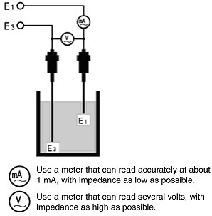
How is the resistance between electrodes of the Level Switches measured?
Since the resistance between electrodes cannot be measured by a tester, use an ammeter able to read approximately 1mA with as low an impedance as possible and a voltmeter able to read a value of several volts with as high an impedance as possible to measure the current and voltage between electrodes.
Calculate a resistance value from the measured voltage and current values by using Ohm's Law.
As for the resistance between electrodes, refer below.
* Perform the measurement while the Floatless Level Controllers "61F" unit is wired to each end of electrodes E1-E3.
An ammeter able to read approximately 1mA with as low an impedance as possible
A voltmeter able to read a value of several volts with as high an impedance as possible
Can 61F Floatless Level Controllers be used only for liquid level detection in order to output a signal, without turning a pump ON or OFF?
Yes, this is possible by disconnecting E2 self-holding circuit.
However, when there are waves on the liquid surface, 61F will also repeatedly turn ON and OFF, so the lifetime of the contacts will be shorter than usual.
61F-G/61F-GH/61F-GD/61F-GR/61F-GL 2km/61F-GL 4km/61F-G-TDL/61F-GT
61F-GN/61F-GNH/61F-GND/61F-GNR
61F-GP-N/61F-GP-NL 2km/61F-GP-NL 4km/61F-GP-NH/61F-GP-ND/61F-GP-NR/61F-GP-N8/61F-GP-N8L 2km/61F-GP-N8L
4km/61F-GP-N8H/61F-GP-N8D/61F-GP-N8R
61F-UHS/61F-GP-N15/61F-GPN-BT/61F-GP-N8HY
Can you explain the wiring for combining 61F-G Floatless Level Controllers with an upper-limit float switch and a lower-limit float switch in order to control upper and lower limits?
Connect the upper-limit float switch (SPST-NO output) between the E1 and E3 terminals of 61F-G, and connect the lower-limit float switch (SPST-NO output) between the E2 and E3 terminals of 61F-G.
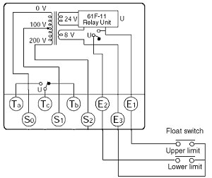
However, because only about 1 mA flows between 61F electrodes at 8 VAC, be sure to use microload contacts.
Applicable model: 61F-G
What does "operation resistance" mean?
This is the resistance between electrodes that is required for the 61F Floatless Level Controllers and K7L Liquid Leakage Sensors to operate. The 61F and K7L will definitely operate when the liquid or solid inter-electrode resistance value is lower than the operation resistance value.
The higher this value is, the easier it is for the Level Controller to operate even with low-conductivity liquids, thus raising the sensitivity of the Level Controller.
Is there a way to tell whether the sensitivity of 61F Floatless Level Controllers is suitable for the liquid being used?
Yes, measure the interelectrode resistance both while Electrodes are immersed in the liquid and while they are held away from the surface of the liquid, and see if the values are within the ranges given in 61F specifications.
1. Measure the interelectrode resistance while Electrodes are immersed in the liquid, and check it against the interelectrode operate resistance range in the specifications. If the resistance is higher than the range in the specifications, an operating error may occur. In this case, increase 61F sensitivity or shorten the distance between Electrodes to bring the interelectrode operate resistance to a level within the range given in the specifications.
2. Measure the interelectrode resistance while Electrodes are held away from the surface of the liquid, and check it against the interelectrode release resistance range in the specifications. If the resistance is lower than the range in the specifications, a release error may occur. In this case, reduce 61F sensitivity or increase the distance between Electrodes to bring the interelectrode release resistance to a level within the range given in the specifications.
Note:It is important to select the appropriate 61F model. Selecting one with an interelectrode resistance range that is larger than necessary may result in faulty resetting due to condensation forming in Electrode Holders.
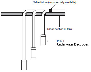
How do I secure underwater Electrodes?
Because underwater Electrodes are often used in wells and other deep places, their cables are long and heavy. This is why an Electrode Holder is not used with these Electrodes. Secure Electrodes onto the tank surface as shown in the following cross-sectional diagram, or wrap them around something. OMRON does not provide any special brackets for this purpose. Use a commercially available bracket if desired.
 Automation Systems
  Motion & Power Solutions
  Safety, Vision and IDENT
  Sensing Solutions
  Control Components
  Switching & Accessories
 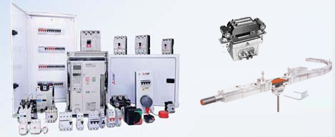 Switchgear and Trolley Systems
 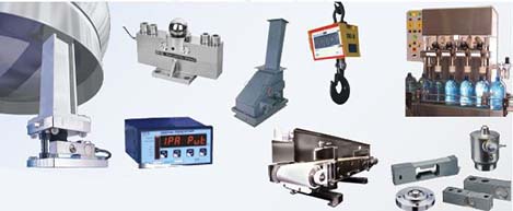 Process Weighing
  LED Lighting
  Omron
Omron
 Mitsubishi
 Delta
Delta
 Autonics
 Inno
Inno
 Honeywell
 Novotechnik
 Orientalmotor
 Microscan
 IPA
IPA
 Technomech
 Intech
 IOT & Traceability
 Project & Panel Engg.
 Application Case Studies
 Solutions by Industry
 Solutions by Process
 Solutions by Product
 Corporate Information
 Company Profile
 Quality Policy
 Mission Statement
 Chairman's Message
 Intech Group Companies
