Frequently asked questions and answers for Programmable Controllers - Industrial Automation
What is the difference between the different operating modes of the Programmable Controller's CPU Unit (i.e., PROGRAM mode, RUN mode, and MONITOR mode)?
In PROGRAM mode, the CPU Unit is stopped. User programming can be created or modified, memory can be cleared, programs can be checked, programs can be debugged, and I/O memory tables can be created or modified.
In MONITOR mode the CPU Unit is running. I/O is processed in the same way as in RUN mode. The operating status of the CPU Unit can be monitored, bits can be force-set/reset, the set values and present values of timer and counter instructions can be modified, and the present values of word data can be modified. MONITOR mode is used for system adjustments during trial operation.
RUN mode is used for normal system operation. The operating status of the CPU Unit can be monitored, however bits cannot be force-set/reset, and present values and set values cannot be modified using Programming Devices.
The operating mode can be changed using a Programming Device or by sending a command using Host Link communications.
Is there an instruction that can be used in a subroutine to turn OFF an output bit that was turned ON in the main program?
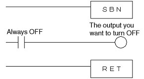
Yes, the RESET instruction (RSET) or Always OFF Flag can be used in a subroutine to turn OFF a bit that was turned ON in the main program
Using the RESET Instruction (RSET)
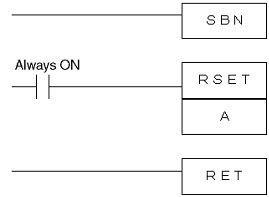
*A = The output you want to turn OFF
Using the Always OFF Flag
Will interrupt tasks and interrupt subroutines work properly during overhead processing, I/O refreshing, and peripheral servicing if C200HS-INT01 Interrupt Input Units are used in CS1 or CS200HX/HG/HE Programmable Controllers?
Yes, if an interrupt occurs, the interrupt task will be started even during I/O refreshing or peripheral servicing.
When I turn ON the power to Programmable Controllers, two ruled lines appear on the Programming Console display. What is the problem?
The CPU error display (= = = =) means that a communications error has occurred between Programmable Controllers and the Programming Console.
Sometimes the CPU error display will appear even when the CPU Unit and the Programming Console are functioning normally. The possible reasons for this follow. Check each point to identify the problem.
When the Power to an Expansion Rack Has Been Interrupted
When the Switch Setting Is Incorrect
Other CPU Unit models do not have switch settings, so this does not need to be checked.
When There Is a Power Supply Failure
Of course, it is possible that the Programming Console itself has failed, so check to see whether or not it will operate properly on another CPU Unit.
This applies to C200H-PRO27-E, CQM1-PRO01-E, and CQM1H-PRO01-E Programming Consoles.
How will Programmable Controllers behave if the power supply voltage drops momentarily?
The Programmable Controllers behaves in the following ways if the power supply is interrupted or the power supply voltage drops.
Is a battery for EEPROM memory backup required when using an EEPROM Memory Cassette with C200HS or C200HX/HG/HE Programmable Controllers?
No, the EEPROM Memory Cassette does not require a battery.
Can NT-AL001-E RS-232C/RS-422 Link Adapter be used to convert the peripheral port on a CPU Unit of Programmable Controllers to RS-422?
No, the peripheral port on the CPU Unit of Programmable Controllers do not supply 5 V, so the NT-AL001-E cannot be connected. Use an RS-232C port.
Can I continue to use CQM1-CIF01 or CQM1-CIF02 Peripheral Port Connecting Cable that I am currently using with CQM1 even if I change to CQM1H Programmable Controllers?
Yes, but you will need to connect CS1W-CN114 Connecting Cable to the CQM1-CIF01 or CQM1-CIF02 to connect to the CQM1H.
Can the contents of the DM Area in CS1 or C200HX/HG/HE Programmable Controllers CPU Units be written to or read from a personal computer even when the CPU Unit is operating?
The DM Area can be written to or read from a computer even while the CPU Unit is operating. When the CPU Unit is in MONITOR mode, both reading from the CPU Unit to the computer, and writing from the computer to the CPU Unit are possible. When the CPU Unit is in RUN mode, only reading from the CPU Unit to the computer is possible. The DM Area can be written to or read using WS02-CXPC1-J FA Integrated Tool Package (CX-Programmer), or using user programming on the computer.
What problems will occur if I mistakenly set CQM1 Programmable Controllers as the device type when programming CPM2C Programmable Controllers using the SYSMAC Support Software?
CPM2C memory contains the following:
Input bits: CIO 0 to CIO 9, output bits: CIO 10 to CIO 19, word bits: CIO 20 to CIO 49 and CIO 200 to CIO 227.
Therefore a memory error will occur if a program uses CIO 50 to CIO 199, which do not exist in the CPM2C.
(Programs created using the CX-Programmer FA Integrated Tool Package will check for the useable memory areas. However, the device type is set to CQM1 when using the SYSMAC Support Software, so the check for the usable memory areas, which is normally performed when using CPM2C, will not be performed. Memory areas that are not supported by CPM2C can be inadvertently used for programming and data transfer.)
If a memory error occurs, check the programming to see whether a memory area that is not supported by CPM2C is being used.
( Check for the following: CIO 50 to CIO 199, HR 20 to HR 99, and LR 16 to LR 63, as well as addresses in the TIM, CNT, and DM areas.)
After correcting any errors, transfer the corrected program to the CPU Unit.
When we communicate with Personal Computer at Programmable Controller Peripheral Port, which is faster between Host Link and Tool bus?
Host Link communicates with ASCII code but Tool bus uses Binary code.
Data quantity by binary is double than that of Host link even when the communication speed are same
Is there Programmable Controller simulation software?
Yes by CX-Simulator for SYSMAC CS1 only.
How can we convert SYSMAC Support Software file SP1 by CX-Programmer FA Integrated Tool Package?
After CX-Programmer Ver.2.1
Able to read it directly.
Select the FILE OPEN function on menu, then we can save as SP1 file: SYSMAC support soft ladder program (*SP1).
Before CX-Programmer Ver.2.1
File Conversion Utility convert SP1 file specifying CXT file to read SP1 File.
Then we can save as CXT file. Then we can open CXT file by CX-Programmer.
What is the difference between files with the extension .CXT and .CXP that can be converted using the CX-Programmer FA Integrated Tool Package conversion utility?
CXT files (.CXT extension) are created when data from the older Support Software is imported into the CX-Programmer. CXT files are saved in text format, which can be easily read by the CX-Programmer and other utilities and applications.
Files that were created with the CX-Programmer are saved as CXP files (.CXP extension). The contents of CXP and CXT files are the same, but CXP files are compressed binary files. CXP files have a smaller file size allowing them to be easily saved on disks, and they can be processed at high speed.
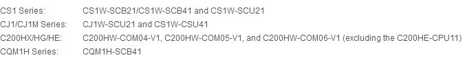
Programming Support Software for C500
SYSMAC Support Software supports programming function for C500 Cable and units combination is:
(1) Interface unit C200H-IP007 + Cable CQM1-CIF01 (PC98), CQM1-CIF02 (DOS/V)
(2) Host Link Unit C120-LK201-V1 + Cable XW2Z-200P (2m), XW2Z-500P (5m)
*The XW2Z-500P is a PC98 Type Cable. The XW2Z-500P-V is a DOS/V Type cable.
Can Factory Automation System Integrated Tool Package "CX-One CX-Programmer" and Drawing Tool for CX-One NS Series "NS-Designer" be connected with the Programmable Controllers (PLC) by using a USB port built into the personal computer?
Use the D-sub to USB-Serial Conversion Cable "CS1W-CIF31". This cable can connect the Programmable Logic Controller "SYSMAC" and/or the Programmable Terminal "NT/NS Series" with the support software.
Please consult your OMRON representative about the execution times for individual instructions.
Since Windows softwares including the CX-Programmer and the NS-Designer use the Windows COM port which does not depend on its physical configuration: RS-232C or USB port, either connector can be used. However, since the performance of a commercially-available simple USB-RS232C conversion connector for hobby use may not meet the high-speed communication, utilize a USB conversion cable suitable for FA use
* "Windows" is a registered trademark of Microsoft Corporation.
What is the correct device type setting in the Support Soft Ware "CX-Protocol" when creating send/receive sequences for protocol macros for CQM1H Programmable Controllers?
Select C200HG Programmable Controllers for the device type, select CPU43 for the model, and turn ON pin 8 on the DIP switch on the front panel of CQM1H.
What are FINS commands?
"FINS" stands for Factory Interface Network Service, which is protocol for sending messages between controllers on OMRON FA networks. The user can provide measures (e.g., in the user application) such as retry processing to ensure that transmitted messages arrive at the destination node.
What is the best way to monitor I/O Memory Data of the CS1, C200HX/HG/HE, CPUs in Excel files?
Programmable Controller reporter provides Data collection at Excel loading the input data from CIO or DM area of Programmable Controller pasted at the cells of excel file only by settings.
It is also possible to download (writing) data from the cells to the Programmable Controller.
Applied OS is the Windows95/98, and supported Excel is the Excel97 and Excel 2000.
Supported communication between Personal Computer and Programmable Controller is Host Link (1:N), Controller Link, SYSMAC LINK, and Ethernet
Models are the SDKY-95HLK-E97 for Host Link and the SDKY-95MLT-E97 for other network.
* "Windows" is a registered trademark of Microsoft Corporation.
Without using FINS Communication, can we access Programmable Controller I/O memory via Ethernet?
FTP server function of Ethernet Unit provides Data read or write for Memory card or EM File Memory. TCP/IP, UDP/IP Protocol provided Socket service. Socket service provides sending or receiving data and further processing by ladder program to change the memory at Programmable Controller.
Is there a command that can write 100 words of data at once from a computer to the DM Area in the CPU Unit?
Yes, a FINS (Factory Interface Network Service) command is supported for CS1-series and CVM1/CV-series Programmable Controllers. This command is used to write 100 words of data all at one time. However, only the CS1-series and CVM1/CV-series support this command. When using C-series Programmable Controllers, the data must be written 4 times, writing 30 words each time. Therefore 100 words of data cannot be written simultaneously when using C-Series.
What part of I/O memory in the CPU Unit is allocated to CS1W-SCU21 Serial Communications Unit and CS1W-CLK21 Controller Link Unit?
CS1W-SCU21 and CS1W-CLK21 are both CPU Bus Units. Words are allocated to CPU Bus Units according to the unit numbers set on the front of the Units. The first Word that is allocated is "n" and corresponds to CIO 1500 + 25 x unit number. For setting details, refer to the relevant manual.
When using a SYSMAC LINK Unit with a C1000H/C2000H Programmable Controllers CPU Unit that already has a 3G2A5-LK201-EV1 Host Link Unit, is it necessary to replace 3G2A5-LK201-EV1 with a C500-LK203 Host Link Unit?
Yes. The 3G2A5-LK201-EV1 cannot be used together with the SYSMAC LINK Unit, so switch to the C500-LK203.
When I use C120-LK201-EV1 Host Link Units with C60P Programmable Controllers, a communications error occurs. Why?
C120-LK201-EV1 cannot be used with C60P. Use 3G2C7-LK201-EV1 Host Link Units instead.
Can a single sensor output be connected to multiple Programmable Controllers Input Units in parallel?
The conditions for setting up this type of connection are as follows:
The following formula must be satisfied by the above conditions.
How can we use Programmable Controller Transistor Output distinguishing Sink Type or Source Type?
Plus common or Minus common depends on the connected equipment. Sink Type has Minus COM, Current flows from Load to Unit when turned on. Source Type is reversed, COM is plus, Current flows from Unit to Load when turned on.
What is the allowable momentary power interruption time for the CQM1-PA203/-PA206/-PA216/-PD026 Power Supply Units?
If the power is interrupted for less than 10 ms when using a CQM1-PA203/-PA206/-PA216, the Programmable Controller will continue to run normally.
If the power is interrupted for more than 25 ms, the power interruption will be detected, the CPU Unit will stop, and the outputs will turn OFF.
A power interruption that lasts more than 10 ms but less than 25 ms may or may not be detected. Operation in this case cannot be predicted.
If the power is interrupted for longer than 5 ms when using a CQM1-PD026, the power interruption will be detected, the CPU Unit will stop, and the outputs will turn OFF.
How long are the contents of the DM Area in a CS1 Programmable Controllers or C200HX/HG/HE Programmable Controllers CPU Unit retained?
CS1 and C200HX/HG/HE include a battery as a standard feature. The contents of the DM Area will be retained as long as the battery retains its charge.
The contents of the DM Area will be backed up for at least 5 minutes.
What is the difference between Group-2 High-density I/O Units and Special I/O Units used with the CS1 Programmable Controllers and C200HX/HG/HE Programmable Controllers?
Both have limits on the maximum number of Units that can be mounted according to the CPU Unit model. Group-2 High-density I/O Units can be mounted to the CPU Rack or Expansion Racks, but cannot be mounted to SYSMAC BUS Slave Racks.
The Special I/O Units can be used on CPU Racks, Expansion Racks, and the SYSMAC BUS Slave Racks.
When will the RUN output on C200HW-PA204R Power Supply Units for CS1 Programmable Controllers and C200HX/HG/HE Programmable Controllers turn ON?
The RUN output on C200HW-PA204R will turn ON when the CPU Units are in MONITOR Mode or RUN Mode as long as a fatal error has not occurred.
Normally, the RUN output turns ON approximately one second after the CPU Units power is turned ON. The RUN output will turn OFF when the CPU Units enter PROGRAM Mode or a fatal error occurs.
Using CX-Programmer FA Integrated Tool Package, how can we connect Programmable Controller via Ethernet?
1) Personal Computer Model Change / [Network Type] is set [Ethernet].
2) Click [Setting], set FINS destination address [Network] / [Node]
(Node = Ethernet Unit Node Number, Network = Network address set in Routing table)
3) Check Automatic generation method at [Driver] tab / Workstation node Address. Port Number = 9600.
I have connected a C200H-PRO27-E Programming Console to a CQM1H Programmable Controllers peripheral port and am running the CPU Unit in MONITOR mode. However, when I turn OFF power supplies to CPU Units, remove Programming Console, and then turn ON power supplies again, CPU Units do not enter RUN Mode. What is the cause of this, and how can I resolve this problem?
If you turn OFF power supplies to CPU Units while the pin 7 on the DIP switch on the front of CPU Units are OFF, CPU Units will enter PROGRAM Mode when power supplies are turned ON again. Therefore, be sure to turn OFF the power to the CPU Unit with pin 7 on the DIP switch turned ON. Alternatively, you can set the operating mode in Programmable Controllers Setup to enter RUN Mode (set DM6600 to 0202) when power supplies are turned ON.
What is the difference between CS1W-NC[]13 Position Control Units and CS1W-MC221 Motion Control Units?
The differences between CS1W-NC[]13 and CS1W-MC221 are as follows:
Control target: Stepping Motor Drivers
Servo Motors with pulse strings
Direct Drive Motor Drivers
Control language: Ladder programming is good for simple ladder operations (direct operation or memory operation), however complex operations place a heavy load on the ladder program.
Control target: Servo Drivers with analog inputs
Can connect to OMRON Servo Drivers that support absolute values.
Control language: Multitask G-language (G-language program is started from the ladder program.)
Multitask G-language allows for simple programming and is widely used for NC machine tools and position control. The load on the ladder program is light.
Others: Can be connected to a manual pulse generator (MPG).
I have C200H-MC221 Motion Control Units connected to a servo driver from another company. What is required for the DRV X-Y Connector XSOUT signal (SEN signal), and what timing is required?
The XSOUT signal (SEN signal) is used to load the present motor position when connecting OMRON Drivers that support absolute values (R88).
(By using Motion Controllers with OMRON Servo Drivers/Servomotors, an absolute system that does not need to search for the origin can be easily constructed.)
Therefore, the XSOUT signal (SEN signal) is not required when connecting servo drivers from another company. As for the timing, the SEN signal will turn ON when Motion Control Units power supplies are turned ON (i.e., when power supplies for Programmable Controllers are turned ON). The SEN signal will turn OFF when Servomotors are locked.
Can C200H Group-2 High-density I/O Units be used with C200H-RT201 SYSMAC BUS Remote I/O Slave Unit?
No, C200H Group-2 High-density I/O Units cannot be mounted to a Slave Rack created with the C200H-RT201. Use 16-point I/O Units instead.
Can CQM1 Programmable Controllers programs be used on CQM1H Programmable Controllers without modification?
Yes, CQM1 programs can be used on CQM1H without modification. When transferring data from the Support Software, a different device type must be set.
What are the conditions under which a C200HX/HG/HE Programmable Controllers will detect a power interruption when used with C200HW-PA204 Power Supply Units at 100 VAC?
A power interruption to C200HX/HG/HE will be detected under the following conditions. If the power supply voltage drops below 85% of the rated voltage, the CPU Unit will stop and the outputs will turn OFF depending on the length of the interruption.
The CPU Unit will not respond to the power interruption and will continue to run unconditionally if the power is interrupted for less than 10 ms.
If the power interruption lasts more than 25 ms, the system will stop, and outputs will turn OFF.
If the power interruption lasts more than 10 ms but less than 25 ms, the CPU Unit may or may not respond to the power interruption. In this case, the operation of the CPU Unit cannot be predicted.
The time it takes to detect a power interruption can be extended using a setting in the Programmable Controllers Setup (DM 6605).
How do I use the calendar and time data with CS1 Programmable Controllers and C200HX/HG/HE Programmable Controllers CPU Units?
CS1 and C200HX/HG/HE CPU Units support clock functions (excluding the C200HE-CPU11-E) as a standard feature. Use the words containing the clock data for programming. The words used for click data depends on the model, so refer to the operation manual.
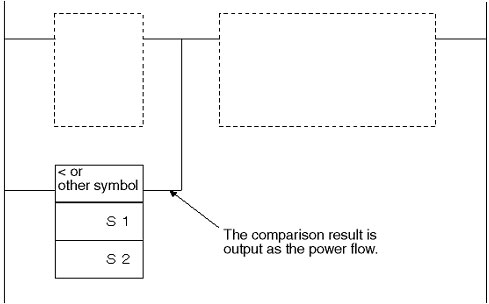
Are there comparison instructions that can be used as the input condition for other instructions in a ladder program?
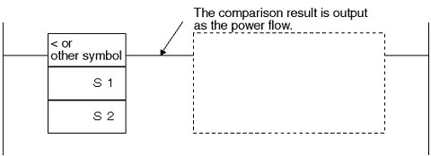
In a CS/CJ-series Programmable Controllers CPU Unit, compare instructions can be used as input conditions by using Symbol Comparison Instructions.
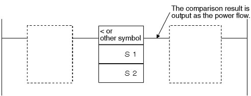
Symbol Comparison instructions come in the three forms, LD, AND, and OR.
The AND-type symbol comparison instruction can be used with the CVM1-V2 Programmable Controllers and C200HX/HG/HE-Z Programmable Controllers CPU Unit.
The C-series Programmable Controllers CPU Units do not support Symbol Comparison Instructions.
Is it possible to connect two CPM1A Programmable Controller Units with a RS-232C cross cable through an adapter, process an input to one CPM1A Unit, and output the result from the other CPM1A Unit?
Data in the LR Area can be transferred using a CPM1A 1:1 link. Transfer the necessary data to the LR Area to use this function. DM 6650 must be set to use a 1:1 link. In this case, the baud rate will be set to 19,200 bps and cannot be changed.
When I used C120-LK201-EV1 Host Link Units with C20P Programmable Controllers a communications error occurred. How should I handle this?
C120-LK201-V1 cannot be used with C20P. Use the 3G2C7-LK201-EV1 instead.
Will a CS1-series Programmable Controller's program be lost if its backup battery is not replaced after its 5-year service life has expired?
The program will not be lost as long as the Programmable Controller's power supply does not go OFF.
The battery service life is 5 years, so replace the battery every 5 years to prevent problems such as electrolyte leakage.
Can we send string data from the Programmable Controllers via the RS-232C interface?
Yes. We can use the TXD instruction to send out string data from RS-232C Port by no protocol communication function.
TXD Instruction can be used with the CQM1/CQM1H, C200HX/HG/HE/HS, and CS1.
Is there a restriction on the number of C200H Programmable Controllers SYSMAC LINK Units that can be mounted when a Host Link Unit is also mounted? Is it different than with C1000H Programmable Controllers?
With C200H, the SYSMAC LINK Units use the Bus Connection Units to exchange data with the CPU Unit.Therefore, there is no restriction on the number that can be mounted for Units that do not use Bus Connection Units (i.e., Host Link Units).
This is different for the C1000H, as shown below.
What upgrades were made to the Backplanes for C200H/HS/HE/HG/HX Programmable Controllers?
C200H-BC[][]1
(next)
C200H-BC[][]1-V1:Supports 16-point Output Units.
(next)
C200H-BC[][]1-V2:Supports the C200HS-INT01 Interrupt Input Units.
C200HW-BC[][]1
(next)
C200HW-BC[][]1-V1:Supports the C200HW-PA209R Power Supply Units.
Can we use the CX-Programmer with the C200H CPU?
Yes. The CX-Programmer Ver.3.0 ( The WS02-CXPC1-JV3/-EV3) is worked for Windows95/98/NT4/Me/2000/XP.
Connection Cable between Personal Computer and Programmable Controllers :
Peripheral interface C200H-IP007: CQM1-CIF02
Host link unit C120-LK201-V1: XW2Z-200S-V
*"Windows" is a registered trademark of Microsoft Corporation.
Why is it that when I use online editing to delete instructions that cause an output on Programmable Controllers to be turned ON, the output does not turn OFF?
If you use the online editor to delete a bit that is ON, the bit will remain ON. This is because the program needed to turn OFF the bit has been removed.
Why communication error occurs during CX-Programmer FA Integrated Tool Package get online with Programmable Controller?
Possible cause to be checked as follows:
What is the difference between CPM2C Programmable Controllers CPU Units with sinking outputs and sourcing outputs?
With sinking outputs, current flows in the following order:
"Positive power supply line" to "Load" to "CPM2C" to "Negative power supply line". This is the same as for an NPN transistor.
With sourcing outputs, current flows in the following order:
"Positive power supply line" to "CPM2C" to "Load" to "Negative power supply line". This is the same as a PNP transistor.
The device being output to will determine whether a sinking or sourcing output should be used.
What is indirect DM addressing?
Indirect DM addressing involves reading the contents of a specified DM word and using it as the address of another word in the DM Area, e.g., to read the contents of the second word.
In a program, this operates as follows:

The constant 0000 is not moved to DM 0100, but rather the contents of DM 0100, which is 0500, is taken as an address in the DM Area and the constant 0000 is moved to DM 0500.
What system configuration is necessary to display the contents of 4-digit decimal data memory in Programmable Controllers on an external 7-segment digital display?
There are two types of digital display units, static output models and dynamic output models. If the data from only one 4-digit decimal display needs to be displayed, it is recommended to use static models to make system maintenance easier.
Also, among static models, there are models with positive logic and models with negative logic. Negative logic (see note) is much more common among Output Units for Programmable Controllers, so we recommend using models with negative logic.
Note:C200H Programmable Controllers Output Units with negative logic include the C200H-OD215, C200H-OD218, and C200H-OD219. Select a M7E Digital Display Units with negative logic.
What is a protocol macro?
A protocol macrois macro containing a communications protocols designed for the communications specifications of an external device that has a serial communication port.
The following two main functions are provided for protocol macros.
The Boards and Units are equipped with communications protocols to send and receive data with OMRON CompoNet components (e.g., Temperature Controllers, Digital Panel Indicators, Barcode Readers, and Modems). Therefore, data communications with OMRON components can be achieved by simply setting the data to be sent or received, and executing the PMCR(260) instruction.
The following products support protocol macros.
Can a C200H-NC111/112/211 Position Control Units be used in a CS1-series Programmable Controllers? Are there any restrictions?
Yes, the C200H-NC111/112/211 can be used in CS1-series Programmable Controllers.
The NC112 and NC111 are allocated 10 words, and the NC211 is allocated 20 words. The unit number range for the NC112 and NC111 is 0 to 9. The unit number range for the NC211 is 0 to 8.
How can the Programmable Controller "SYSMAC" be connected to a personal computer through a serial port or an Ethernet? Is the FinesGateway necessary?
In the case of serial interface
There are two ways: using the FinsGateway Ver.3 or not using it.
In the case when an application to be developed with the VisualC++ or the VisualBasic may be used through other interface methods, it is better to utilize the FinsGateway Ver.3.
On the other hand, in the case when the connection is done only through a higher-level link, it is possible to open a COM port directly from the VisualC++ or to issue a higher-level link command disclosed in the manual by using the VisualBasic and the ActiveX Control for commercially available serial access without using the FinsGateway Ver.3.
In the case of Ethernet interface
There are two ways: using the FinsGateway Ver.3 or not using it. In the case when an application to be developed with the VisualC++ or the VisualBasic may be used through other interface methods, it is better to utilize the FinsGateway Ver.3.
On the other hand, in the case when the connection is done only through an Ethernet interface, it is possible to call up the WinSock2 library directly from the VisualC++ or to issue FINS/UDP/IP commands disclosed in the manual by using the VisualBasic and the ActiveX Control for commercially available WinSock2 without using the FinsGateway Ver.3.
Is there a cable available that will connect the built-in RS-232C port of CS-series Programmable Controllers CPU Unit to NT-AL001 Option of Programmable Controllers?
Yes, XW2Z-070T-1 (70 cm) and XW2Z-200T-1 (2 m) Cables.
These cables can also be used to connect the C200HX/HG/HE or CQM1H Programmable Controllers to the NT-AL001 RS-232C/RS-422A Link Adapter.
What is the difference between C200H-ID216 Programmable Controllers' input Units and C200H-ID218 Programmable Controllers' input Units?
The C200H-ID216 and C200H-ID218 have different input impedances. The input impedance of each Unit follows.
C200H-ID218: 3.9 kΩ
C200H-ID216: 5.6 kΩ
Therefore, their input currents are also different.
C200H-ID218: 6 mA
C200H-ID216: 4.1 mA
Choose Units based on the leakage current of the connected devices.
With the CX-Programmer FA Integrated Tool Package, what is the procedure to transfer a program to a C200HX/HG/HE-Z Programmable Controllers or C200HS Programmable Controllers Memory Cassette? What is the procedure to verify the data?
The procedure to write data to a Memory Cassette and perform verification follows.
What is the baud rate of the RS-232C communications port built in to CS1 Programmable Controllers CPU Unit?
The maximum baud rate when CS or RS control wires are wrapped at ends of the cable is 19,200 bps. When CS or RS control wires and hardware flow control are being used, the maximum achievable baud rate is 38,400 bps in most cases.
When, for example, using a baud rate of 56,000 or 115,200 bps on a laptop computer with the CX-Programmer FA Integrated Tool Package, the hardware chipset, Windows version, installed drivers and application software are all factors that may affect the system, causing stable operations at times and communications errors at other times.
*Windows is a registered trademark of Microsoft Corporation.
What is the minimum version of the CX-Programmer FA Integrated Tool Package required to operate in a Windows XP environment?
CX-Programmer Ver.3 is compatible with Windows XP.
The following table shows which CX-Programmer versions are compatible with each Windows operating system.
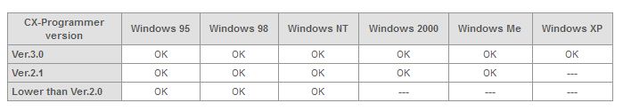
Note:Windows is a registered trademark of Microsoft Corporation.
Which OMRON products (general-purpose communications components) can the CPM2C-CIF21 Simplified Communications Unit communicate with?
CPM2C-CIF21 can perform simplified communications if the connected device is an OMRON Temperature Controllers, Digital Panel Indicators, or Timers.
Communications with general-purpose devices is done using SYSWAY or CompoWay/F commands using a command/response method. Therefore, a connection cannot be established when information flows one-way from the connected device, such as with barcode readers.
Only the following models can be connected:
When using C200H-CT001-V1/CT002/CT021 High-speed Counter Units, the RUN indicator does not light even when I turn ON power supplies to Programmable Controllers. Is the Unit malfunctioning?
The RUN indicator on High-speed Counter Units lights when count operations begin. The conditions under which count operation will begin depend on the operating mode.
Example:
Using C200H-CT001-V1 in Linear Operating Mode
When bit 00 of word n allocated to the High-speed Counter Unit turns ON, the counting operation will begin, and the RUN indicator will light.
n = 100 +10 x Unit number for the C200HX/HG/HE, C200HS, or C200H
n = 2000 + 10 x Unit number for a CS1-series Programmable Controllers
What is the advantage of using index registers?
The most beneficial use of index registers is to reduce the number of steps required in ladder programming.
When processing a continuous or uniformly spaced list of addresses in a ladder program, the exact same programming pattern may appear 10 to 20, or even hundreds of times. This can be true for sequence control (bit processing) and data processing (word processing) as well. In these situations, the number of steps used in a ladder program can be greatly reduced by using an index register in a FOR-NEXT loop.
The CVM1, CV500/CV1000/CV2000, and CS1/CJ1 Programmable Controllers' support index registers.
Is it necessary to create I/O tables when using CJ1 Programmable Controllers?
There are two ways to allocate I/O with CJ1.
If a Unit connection check (using Programming Devices to verify that the Units registered in the I/O tables are actually present) or word reservations are required, the user must create the I/O tables or the user must transfer them to the CPU Unit.
What is the difference between C1000H/C2000H-CPU01 Programmable Controllers and C1000H/C2000H-CPU01-V1?
C1000H/C2000H-CPU01-V1 supports SYSMAC LINK.
C1000H-SLK21-V1 SYSMAC LINK Units can be used for coaxial cable, and C1000H-SLK11 can be used for fiber optic cable.
With C1000H/C2000H-CPU01-V1, up to two of the following Units can be used: Host Link Units (C500-LK203 and C500-LK103), SYSMAC NET Units (C500-SNT31-V4), and SYSMAC LINK Units (C1000H-SLK21-V1 and C1000H-SLK11).
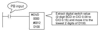
How do I create a program to input 2-digit BCD data from a digital switch to CIO 0.08 to CIO 0.15 and then move the data to specified DM Area words?
Assuming that CIO 0.00 to CIO 0.07 are allocated to other input bits, the following two conditions must be met to create the program.
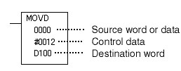
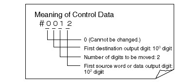
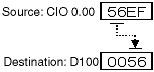
The MOVE DIGITS instruction (MOVD) can be used to meet the conditions described in items 1 and 2 above.
Additional Information
What Is a Digit?
A "digit" is a single numeral. In this case, the instruction name MOVE DIGITS comes from the meaning to send a BCD value in digit (4-bit) increments.
Program
Operation
Note:For details on the MOVE DIGITS instruction (MOVD), refer to the Instructions Reference Manual for the relevant Programmable Controllers.
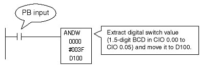
How do I create a program to input 1.5-digit BCD data to CIO 0.00 to 0.05 BCD from a digital switch and move it to a specified DM Area word?
Assuming that CIO 0.06 to CIO 0.15 are allocated to other inputs, only the data in the 6 bits in from CIO 0.00 to CIO 0.05 should be extracted to create this program. If the extracted number of bits were integral multiples of 4 bits (1-digit BCD) the MOVE DIGITS instruction (MOVD) could have be used, but this time 6 bits have been extracted so the MOVD instruction cannot be used. Instead, the LOGICAL AND instruction (ANDW) will be used.
Programming
Operation
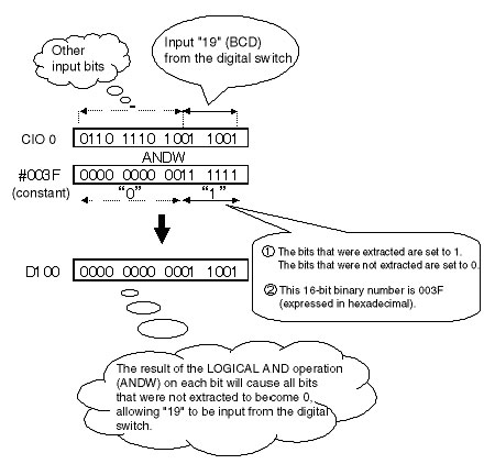
Note:For details on the LOGICAL AND operation (ANDW), refer to the Instructions Reference Manual for the relevant Programmable Controllers.
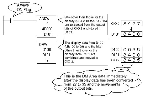
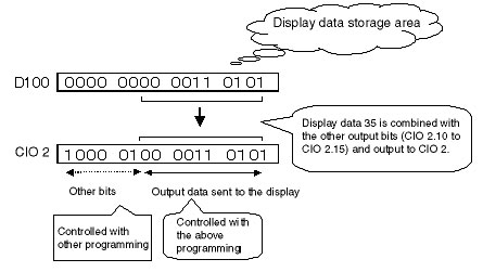
How do I make a program to transfer a 2.5-digit BCD data stored in the DM Area to display it on a static-input digital display (CIO 2.00 to CIO 2.09)?
We will assume that CIO 2.10 to CIO 2.15 are allocated to other output bits. The main point of this program is how to process the combination with the other output bits. This time, we will combine the bits using the LOGICAL AND (ANDW) instruction and LOGICAL OR (ORW) instruction.
Note:The display data storage area is D100.
Program and Operation Explanation
When I transfer the program to CPM1A Programmable Controllers using the SYSMAC Support Software, a message saying to turn ON the Programmable Controllers' DIP switch and try again was displayed. Why?
The default CQM1 Programmable Controllers function codes for expansion instructions must be used on the CPM1A. They cannot be changed. The message will appear if the function code for any of the eighteen expansion instructions has been changed when a program is transferred. If this message appears, return to the CQM1 default function codes for expansion instructions and use them in programming.
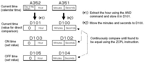
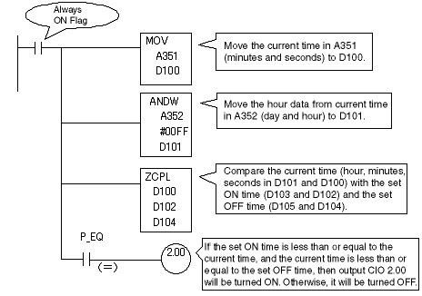
How do I program a time switch to turn ON and OFF a machine at specific time daily?
A time switch like the one you described can be easily programmed using the clock built into the CPU Unit.
Program and Operation Explanation
Store the desired times to turn ON or OFF a particular machine in DM Area words of your choice. Then use the DOUBLE AREA RANGE COMPARE instruction (ZCPL) to continuously compare the time on the clock built into the CPU Unit to the time stored in the DM Area, the turning ON and OFF of machines and devices can be controlled individually.
Note:When using CS1/CJ1 Programmable Controllers, the output words for the current time from the calendar time (A352/A351) are shown as the word address. Refer to the Programming Manual for the relevant Programmable Controllers.
A message saying that the new code is too large and cannot be transferred to Programmable Controllers due to an online editor limitation was displayed while I was performing online editing. What should I do?
When performing online editing with the CX-Programmer FA Integrated Tool Package, there is no limit to the number of rungs, but the maximum number of words (number of steps) is limited. If the number of words is too great, select a smaller range (thus reducing the number of words) and start online editing again.
With CX-Programmer Ver. 3.1 or higher, the maximum program size that can be handled while online editing is checked not only at file transfer, but it is checked while editing as well. Therefore, a warning message will be displayed if the maximum program size is exceeded during editing.
The SYSMAC Support Software can only simultaneously edit one rung at a time. If that rung exceeds the program size limit, a "program over" error will occur and you will not be able to edit the program.
Limitations for CS/CJ Series Programmable Controllers and CVM1/CV Series Programmable Controllers
The program size limit for CS/CJ Series depends on the communications settings and is 247 steps for toolbus. The program size limit for CVM1/CV Series depends on the communications settings and is 263 words for toolbus. Do not edit the program in a way that would cause the maximum cycle time set in Programmable Controllers Setup to be exceeded. If the maximum cycle time is exceeded, a cycle time exceeded error will occur and operation will stop.
Limitations for C Series Programmable Controllers
C Series has a program size limit of 128 words.
A cycle time exceeded error (non-fatal error) will occur for C200H. If this happens, clear the error.
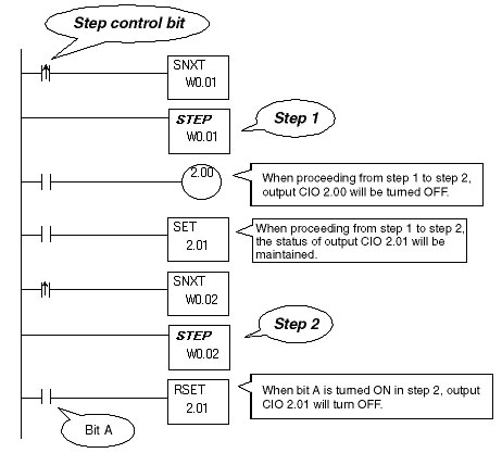
Can I program Programmable Controllers so that all of the outputs in a ladder program step will not turn OFF, even after proceeding to the next step (i.e., will retain the output status in future steps) when using step ladder program instructions to perform step ladder control?
When proceeding to the next step of a ladder program, the OUT instructions will turn OFF all outputs that were turned ON. Therefore, use the SET instruction so that the status of the outputs bits is maintained after proceeding to the next step of a ladder program. When required, turn OFF the outputs using the RSET instruction.
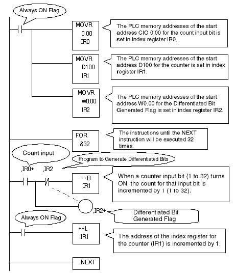
How do I write a program that uses index registers and increment instructions to do an incremental count of N pulse inputs?
The following introduces a method to count 32 pulse input bits within a loop program using FOR-NEXT instructions and an index register. (FOR-NEXT instructions can be used on CS1 and CJ1 Programmable Controllers (PLC).)
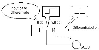
Under basic operating principles, differentiated instructions and instructions with the @ option cannot be used within loop programs. Therefore the program in the following figure has been used.
Basic Structure of a Program to Generate Differentiated Bit
Program
Count input bits: CIO 0.00 to CIO 1.15 (32 bits): Processed with index register IR0
BCD, 4 digits, incremental counter: D100 to D131 (32 bits): Processed with index register IR1
Differentiated Bit Generated Flag: W0.00 to W1.15 (32 bits): Processed with index register IR2
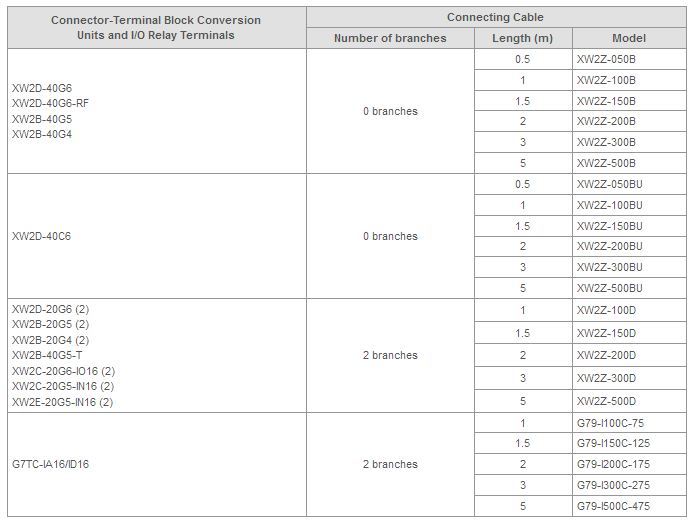
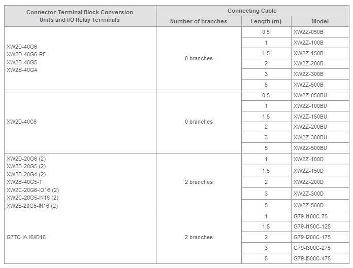
Which Connector-Terminal Block Conversion Units, I/O Relay Terminals, and Connecting Cables can be used with CJ1W-ID231 DC Input Units?
The combinations of Connector-Terminal Block Conversion Units, I/O Relay Terminals, and Connecting Cables that can be used with CJ1W-ID231 are shown in the following table.
The following models can be used with CJ1W-ID231: XW2D-20G6, XW2B-20G5, XW2B-20G4, XW2D-40C6, XW2D-40G6, XW2D-40G6-RF, XW2B-40G5, XW2B-40G5-T, XW2B-40G4, XW2C-20G6-IO16, XW2C-20G5-IN16, XW2E-20G5-IN16, and G7TC-IA16/ID16.
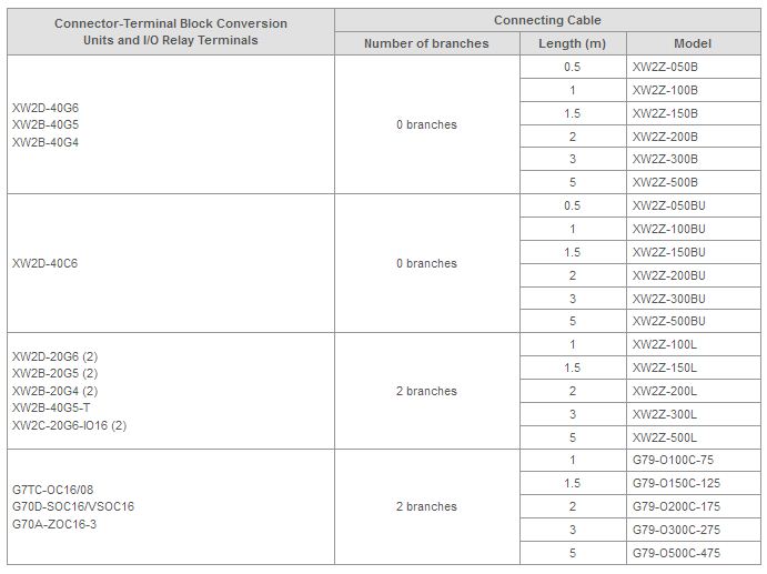
Which Connector-Terminal Block Conversion Units, I/O Relay Terminals, and Connecting Cables can be used with C200H-OD219 Transistor Output Units?
The combinations of Connector-Terminal Block Conversion Units, I/O Relay Terminals, and Connecting Cables that can be used with C200H-OD219 are shown in the following table.
The following models can be used with C200H-OD219: XW2D-40G6, XW2B-40G5, XW2B-40G4, XW2D-40C6, XW2D-20G6, XW2B-20G5, XW2B-40G5-T, XW2B-20G4, XW2C-20G6-IO16, G7TC-OC16/08, G70C-SOC16/VSOC16, and G70A-ZOC16-3.
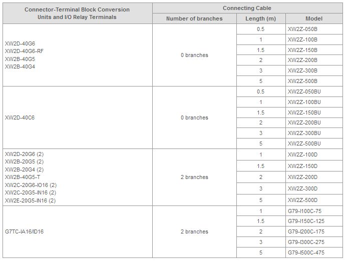
Which Connector-Terminal Block Conversion Units, I/O Relay Terminals, and Connecting Cables can be used with C200H-ID217 DC Input Units?
The combinations of Connector-Terminal Block Conversion Units, I/O Relay Terminals, and Connecting Cables that can be used with C200H-ID217 are shown in the following table.
The following models can be used with C200H-ID217: XW2D-20G6, XW2B-20G5, XW2B-20G4, XW2D-40C6, XW2D-40G6, XW2D-40G6-RF, XW2B-40G5, XW2B-40G5-T, XW2B-40G4, XW2C-20G6-IO16, XW2C-20G5-IN16, XW2E-20G5-IN16, and G7TC-IA16/ID16.
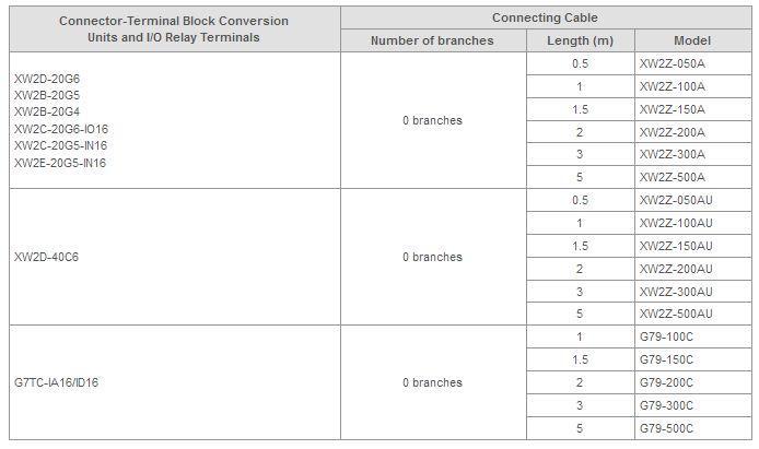
Which Connector-Terminal Block Conversion Units, I/O Relay Terminals, and Connecting Cables can be used with C200H-ID215 DC Input Units?
The combinations of Connector-Terminal Block Conversion Units, I/O Relay Terminals, and Connecting Cables that can be used with C200H-ID215 are shown in the following table.
The following models can be used with C200H-ID215: XW2D-20G6, XW2B-20G5, XW2B-20G4, XW2C-20G6-IO16, XW2C-20G5-IN16, XW2E-20G5-IN16, XW2D-20C6, and G7TC-IA16/OD16.
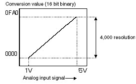
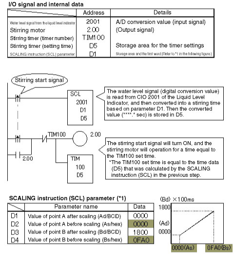
How do I write a program to operate a motor for a time directly proportional to the 1 to 5 VDC signal?
The water level signal (1 to 5 VDC) from the Liquid Level Indicator is an analog signal, so first it must be converted into a digital signal using an Analog Input Unit. The following introduces programming that will convert the digital value into a stirring time (***.* seconds) using the SCALING instruction (SCL).

How do I create programming to use a DATA SEARCH (SRCH) instruction to find a certain product code from within the production instruction master table and extract the related production instruction data?
There are many applications that use the product code as a search key to extract the related production instruction data. The following explains how to use the DATA SEARCH (SRCH) instruction to accomplish this.
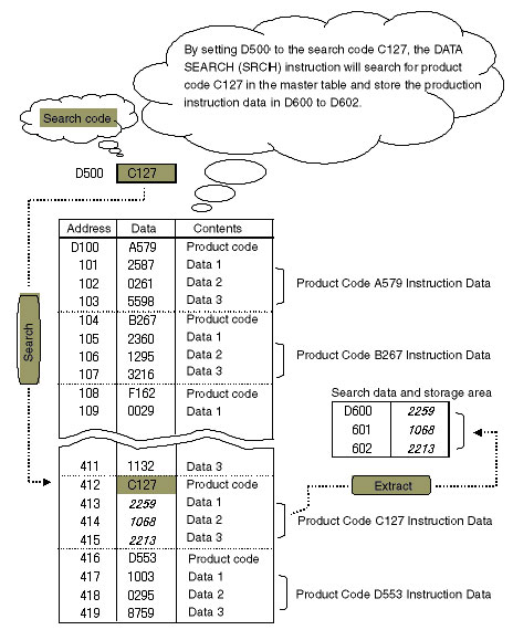
Figure1. Production Instruction Master
*File size: 320 words (80 records at 4 words per record)
*Code specifications: The product code and instruction data cannot have the same code.
The following programming is designed for the CS/CJ Programmable Controllers. When using a C200H Programmable Controllers or other smaller Programmable Controllers, the usage of the DATA SEARCH (SRCH) instruction is slightly different. Before programming, refer to the Instructions Reference Manual for the relevant Programmable Controllers (PLC).
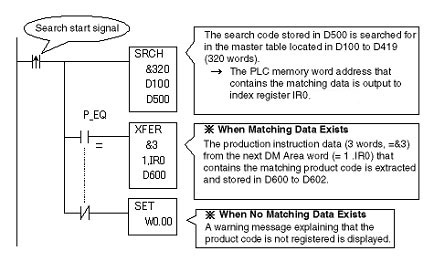
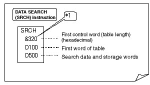
*1. What is &320?
Direct Decimal Input/Hexadecimal Data Formal
When &320 is written, the decimal 320 is converted to hexadecimal 0140 and used as the parameter for the first operand.
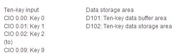
How do I write a program that will read input signals from ten-key keypad connected to a CS/CJ Programmable Controllers and convert them to numeral data?
There are two types of ten-key switches, one that uses binary code and strobe signals, and another that uses decimal code. This document introduces programming for the ten-key switch that uses decimal code.
System Specifications
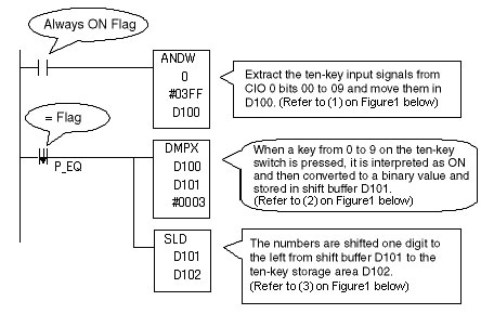
Note:
1.If 5 or more digits are input using the ten-key, then by changing the second operand (shift leftmost word) of the ONE DIGITS SHIFT LEFT (SLD) instruction, the number of useable digits can be extended in 4 digits units.
2.Using the TEN KEY INPUT instruction with the CQM1H Programmable Controllers or C200HX/HG/HE Programmable Controllers will allow a maximum of 8 digit to be input from the ten-key.
What is the difference in the way that the BCD ADD WITHOUT CARRY instruction and BCD ADD WITH CARRY instructions are used?
Most Programmable Controllers support double-length math instructions, but for example, what should be done if the result of a BCD double-length addition operation exceeds the upper-limit of double-length data, which is 9999 9999?
BCD Double-length Data Range
0 to 9999 9999
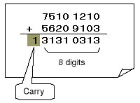
Figure1
How the Carry Flag (CY) Works
The result of the addition operation shown in Figure1 cannot be expressed with only 8 digits, so an overflow (i.e., a "carry") occurs. In this case the Carry Flag (CY) will turn ON.
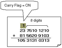
Figure2
Here, the Carry Flag can be used to pass the carry to the calculation for the upper digits, enabling calculations for more than 8 digits.
The information from Figure1 and Figure2 is summarized here.
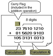
Figure3
Calculation A:
Use the ADD WITHOUT CARRY instruction for rightmost digit calculations in which there is no carry from the lower digit.
Calculation B:
Use the ADD WITH CARRY instruction for upper digit calculations in which a carry from the lower digit must be considered.
The ADD WITH CARRY instruction, as shown in Figure3, is an addition instruction that includes the Carry Flag in the addition operation.
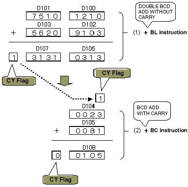
Program and Operation1. Ladder Program
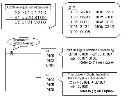
2. Operation
Can C200H, C200HX/HG/HE, or CS Programmable Controllers use the C200H-RM[][][] (SYSMAC BUS) and C200HW-DRM21-V1 (DeviceNet) at the same time?
Normally, C200H-RM[][][] (SYSMAC BUS) and C200HW-DRM21-V1 (DeviceNet) cannot be used together. The DeviceNet Master Unit checks for the existence of Remote Master Units. If Remote Master Units are detected, an E4 error is output, and communications are stopped. Other than communications, the system will operate normally.
A Configurator can be used to solve this problem, allowing C200H-RM[][][] (SYSMAC BUS) and C200HW-DRM21-V1 (DeviceNet) to be used together.
When using a Configurator with C200H or C200HX/HG/HE, do not use the same I/O Area words for C200H-RM[][][] and C200HW-DRM21-V1.
When using the CS, read the master parameters using a Configurator and rewrite them to the CPU Unit to clear the E4 error. The E4 error will be cleared just by writing the parameters to Master Units using the Configurator.
When using the CS, the problem can be solved by using CS1W-DRM21-V1 DeviceNet Unit.
When using together with a SYSMAC BUS Unit, it is recommended to use CS1W-DRM21-V1.
In what cases will the RUN output on a Power Supply Unit turn ON?
The RUN output will turn ON when the CPU Unit is in MONITOR Mode or RUN Mode as long as a fatal error has not occurred.
Normally, the RUN output turns ON approximately one second after the CPU Unit power is turned ON. The RUN output will turn OFF when the CPU Unit enters PROGRAM Mode or a fatal error occurs. The RUN output is enabled only for the Power Supply Unit on the CPU Rack.
Which Connector-Terminal Block Conversion Units, I/O Relay Terminals, and Connecting Cables can be used with CJ1W-ID261 Programmable Controllers?
The combinations of Connector-Terminal Block Conversion Units, I/O Relay Terminals, and Connecting Cables that can be used with CJ1W-ID261 are shown in the following table.
The following models can be used with CJ1W-ID261: XW2D-20G6, XW2B-20G5, XW2B-20G4, XW2D-40C6, XW2D-40G6, XW2D-40G6-RF, XW2B-40G5, XW2B-40G5-T, XW2B-40G4, XW2C-20G6-IO16, XW2C-20G5-IN16, XW2E-20G5-IN16, and G7TC-IA16/ID16.
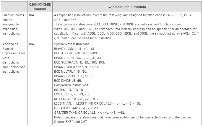
What are the differences in Support Software, instructions, and the way Extended Data Memory is handled between the C200HX/HG/HE Programmable Controllers and C200HX/HG/HE-Z Programmable Controllers?
Refer to the following for information on the instructions that have been added to the C200HX/HG/HE-Z.
Differences between the C200HX/HG/HE and C200HX/HG/HE-Z
Note:Microsoft Windows is a registered trademark of Microsoft Corporation.
What is the difference between the open collector and line driver used with a High-speed Counter Unit?
The encoder specifications determine if an open collector or line driver is needed. Generally the open collector and line driver have the following characteristics.
The open collector operates depending on whether standard voltage is high or low compared to the input voltage. The effect of noise will cause the open collector signal to turn ON or OFF. Noise immunity can be improved by shortening the cable distance, using a shielded cable, or by using a capacitor.
The differential line driver sends a reference voltage along with the voltage as a signal. Because the noise is spread across two lines (both the positive and negative sides), even if there is noise on the cable, the input circuit will not be easily affected. In environments that are easily affected by noise or situations in which the distance the cable must travel is great, it is useful to use a line driver.
What is a CPU error and a WDT error (watchdog timer error)?
A CPU error will occur when the microcomputer in the CPU Unit does not operate properly.
The watchdog timer can be used to check whether the CPU Unit is operating properly.
The watchdog timer is just one way to check whether the CPU Unit is operating properly.
The watchdog timer is a normal processing routine that runs a timer that will be reset if an instruction is executed within a set period of time. If the set period of time passes and the timer is not reset, it is determined that the program has entered an abnormal routine, and an interrupt is generated to detect the error.
This is the method generally used to detect hardware errors.
Take, for example, a program that executes an instruction, and 100 ms later executes the same instruction again. If 130 ms pass and the instruction has not been executed, a hardware error will be detected and program execution will be stopped.
The timer that monitors this time is known as the watchdog timer, and when a specified time has passed, it interrupts program execution and sends notification.
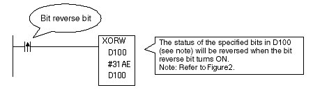
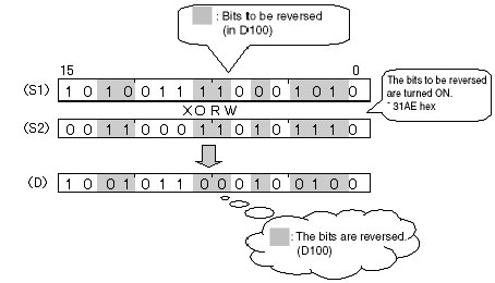
What instruction can I use to reverse the status of specific bits?
Use the EXCLUSIVE OR instruction (XORW) to reverse the status of specific bits in a specific word.
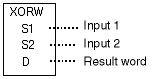
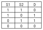
By using this basic specification of the EXCLUSIVE OR instruction (XORW), specific bits in a specific word can be inverted.
1. Ladder Programming
2. Operation
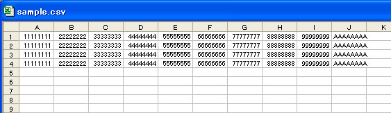
How do I store changeover data in the file memory in CSV format, and use the FREAD instruction to copy the data to specific words in the DM Area?
Refer to control data specifications for the FREAD instruction in the CS/CJ Series Programmable Controllers Instructions Reference.
The file format to read from the Excel file is specified.
The above settings are relevant to the data specifications.
When specifying the CSV format, you specify the number of digits in each data cell when you specify the delimiter.
When using words, the delimiter is placed after every 4 digits. When using long words, the delimiter is placed after every 8 digits.
For the carriage return specification, one field equals one cell.
Example:
Refer to the image of Excel as below.
Create this type of data in Excel and save it in CSV format.
Are there instructions that directly make comparisons (e.g., "equal", "less than", "more than") so that comparison results do not have to be accessed from the status of result flags for comparison instructions?
The following Programmable Controllers support symbol comparison instructions (e.g., "equal (=)", "less than (<)", "more than (>)").
The execution condition for the comparison instruction must be created before the comparison instruction.
How do I write a program to delay turning ON a work bit for 1 scan after an input A turns ON and keep the work bit ON for only 1 scan when using a CS/CJ-series Programmable Controllers?
As shown in Figure 1, the program delays for 1 scan after input A turns ON, and turns ON work bit W2.00 for only 1 scan, as shown in Figure 2.
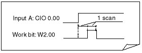
Figure 1
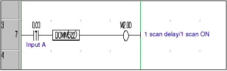
Figure 2
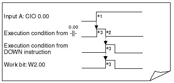
Figure 3
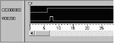
Figure 4
CIO 000000: Input A (CIO 0.00), W00200: Word bit (W2.00)
This programming technique to delay turning ON a work bit for 1 scan after another bit's status changes (i.e., turns ON) and then turn on the work bit for only 1 scan can be used for time limit control between a data output signal and strobe signal in parallel transmissions.
Example of Time Limit Control in Parallel Transmissions
"Transmission request input from a terminal device turns ON" to "Parallel data (n bits) is output".
to "Strobe signal (1 bit) turns ON after 1 scan".
Application Conditions for this Programming
The signal from the device must meet the following time-related conditions.
The time period required between the parallel data and strobe signal must be less than the Programmable Controllers' shortest scan time.
How do I write a program to delay turning ON a work bit for 1 scan after an input A turns ON and keep the work bit ON for only 1 scan?
As shown in Figure 1, the program delays for 1 scan after input A turns ON, and then turns ON work bit W2.00 for only 1 scan, as shown in Figure 2.
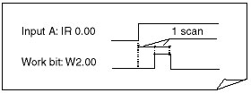
Figure 1
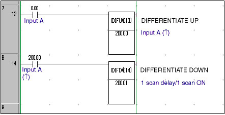
Figure 2
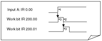
Figure 3
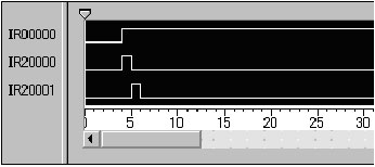
Figure 4
IR00000: Input A (IR 0.00), IR20000: Internal bit IR 200.00
IR20001: Internal bit IR 200.01
This programming technique to delay turning ON a work bit for 1 scan after another bit's status changes (i.e., turns ON) and then turn on the work bit for only 1 scan can be used for time limit control between a data output signal and strobe signal in parallel transmissions.
Example of Time Limit Control in Parallel Transmissions
"Transmission request input from a terminal device turns ON" to "Parallel data (n bits) is output".
to "Strobe signal (1 bit) turns ON after 1 scan".
Application Conditions for this Programming
The signal from the device must meet the following time-related conditions.
The time period required between the parallel data and strobe signal must be less than the Programmable Controllers' shortest scan time.
Note:When using a CS/CJ-series Programmable Controller, a differentiated instruction --|↑|-- and CONDITION OFF instruction (DOWN) can also be used for the same purpose as the above instructions.
How do I program ON/OFF delays?
CIO 000000: Input A (CIO 0.00)
CIO 000200: Output B (CIO 2.00)
*Output B (CIO 2.00) turns ON 3.0 s after input A (CIO 0.00) turns ON (ON delay). Output B (CIO 2.00) turns OFF 1.5 s after input A (CIO 0.00) turns OFF (OFF delay).
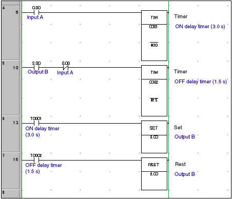
Programming: CS1/CJ1-series Programmable Controllers
*By changing the settings of the ON delay timer (TIM 0001) and OFF delay timer (TIM 0002), the desired delay times can be achieved.
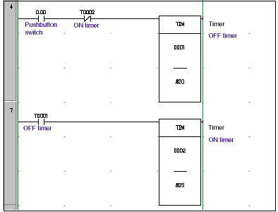
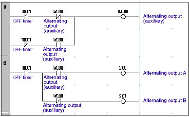
How do I program repeatedly turning a bit OFF for 1 second and ON for 1.5 seconds?
If the ON and OFF time is 0.5 s or 0.1 s, a Clock Pulse Bit (P_ls and P_0_2s) can be used as an input. The following method can be used to create a flicker program that outputs a pulse-train for ON and OFF times for which Clock Pulse Bits are not provided.
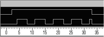
CIO 000000: Flicker start bit (CIO 0.00)
CIO 000200: Flicker bit (CIO 2.00)
*When the flicker start (CIO 0.00) turns ON, the flicker bit (CIO 2.00) is turned OFF for 1 second and ON for 1.5 s. The flicker bit will stop turning ON and OFF when the start bit turns OFF.
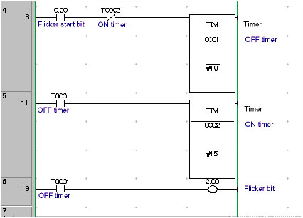
Programming: CS1/CJ1-series Programmable Controllers
*By changing the settings of the OFF timer (TIM 0001) and ON timer (TIM0002), the desired pulse-train output can be achieved.
How do I program a one-shot output?
In a one-shot program, as long as the trigger input stays ON for longer than a certain time (see note), the output bit will be turned ON for a specific period of time regardless of how long the trigger input is ON.
Note:Usually this time is equal to the time of a one CPU Unit cycle.
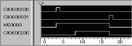
As shown in Figure 1, when the trigger input (CIO 0.00) is ON for either 1.0 s or 2.5 s, the pulse output bit (CIO 2.00) will be turned ON for 1.5 s.
Figure 1
CIO 000000: Trigger input bit (CIO 0.00)
CIO 000200: Pulse output bit (CIO 2.00)
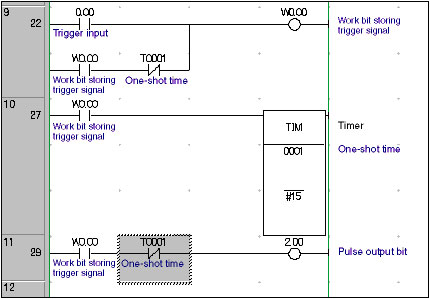
Programming: CS/CJ-series Programmable Controllers
Program Operation
OFF Operation of Pulse Output Bit (CIO 2.00)
What products are recommended as substitutes for the C200H-CPU01 Programmable Controller?
Select any of the following: C200HE-CPU11, C200HE-CPU32, or C200HE-CPU42.
Selection Precautions:
C200HE-CPU11: 3.2 Kwords (built-in RAM)
C200HE-CPU32/42: 7.2 Kwords (built-in RAM)
Points to Check:
C200H-CPU01:
C200H-MR431/MR432/ME431 Memory Unit = 2,878 words
Thus the C200HE-CPU11 is acceptable.
Memory Unit C200H-MR831/MP831/ME831 = 6,974 words
Select from the following: C200HE-CPU32 or C200HE-CPU42 (7.2 K).
C200HE-CPU42: Provides a built-in RS-232C port.
Select from the following: C200HW-BC101-V1, C200HW-BC081-V1, C200HW-BC051, or C200HW-BC031.
(There are no substitute models with the same specifications.)
CQM1-CIF01 and XW2Z-S001 (for PC98, half 14-pin RS-232C)
CQM1-CIF02 (for IBM PC/AT)
How do I program an ON delay?
CIO 000000: Start input bit (CIO 0.00)
CIO 000001: Reset input bit (CIO 0.01)
W00000: Work bit to store start status (W0.01)
CIO 000200: Output A (CIO 2.00)
*Output A (CIO 2.00) will turn ON 2.5 seconds after the start input bit (CIO 0.00) turns ON, and it will turn OFF when reset input bit (CIO 0.01) turns ON.
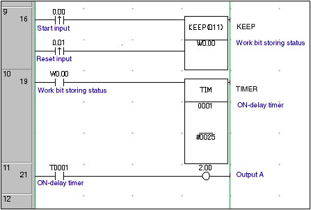
Programming: CS/CJ-series Programmable Controllers
*By changing the setting of the delay timer (TIM 0001), the desired ON-delay time can be achieved.
What is the difference between the CONDITION ON instruction (UP) for the CS/CJ-series Programmable Controllers, and DIFU instruction?
Both the CONDITION ON (UP) and CONDITION OFF (DOWN) instructions were added with the introduction of the CS/CJ-Series, but here we will explain only the CONDITION ON (UP) Instruction.
When the execution condition to UP turns ON, the execution condition output from UP will turn ON for 1 cycle.
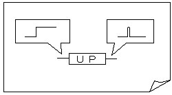
Figure 1
Note:What is PF?
PF is an abbreviation for power flow. The power flow is flow of the execution condition in a ladder program. It runs from left to right, expressing the result of the logical operators (instructions) such as AND, OR, and NOT as a binary signal (ON/OFF).
With the CONDITION ON instruction (UP), you do not have to use a work bit to process the differentiated status, which is necessary with the DIFU instruction. This operation of the CONDITION OFF instruction is shown in Figure1.
The differences between --|↑|--, the DIFU instruction, and the CONDITION ON instruction (UP) are given in Table 1.
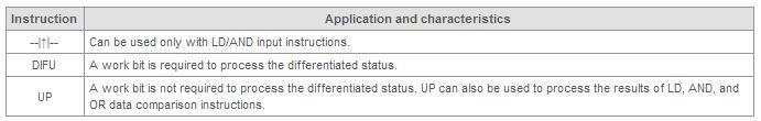
Table 1
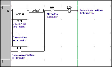
Figure 2
Program Operation
Reference:
We have explained the CONDITION ON instruction (UP) here. The CONDITION OFF instruction (DOWN) is different only in that, when the input signal turns OFF, the execution condition will turn ON for one cycle. The other characteristics of the CONDITION OFF instruction (DOWN) are the same as those of the CONDITION ON instruction (UP).
What outputs turn OFF with in interlocked program sections Interlock Instruction (IL/ILC) and those that do not turn OFF?
The Interlock Instructions can be used to turn OFF all the sequence outputs from a specific program block, as might be necessary to process an emergency stop for one line.
When the execution condition for IL is ON, all bits specified for the following three instructions that are located between IL and ILC instructions in the ladder program will be turned OFF.
Note:This instruction can be used on the following CPU Units: CS1-H/CJ1-H/CJ1M Programmable Controllers.
Ladder Program Sequence When Interlock Is Not Active
Refer to Figure 1.
* The execution condition for the IL instruction is ON.
The instructions between the IL and ILC instructions will be executed as normal.
Outputs A to D (CIO 2.00 to CIO 2.03) are all ON.
SINGLE BIT OUTPUT (OUTB) Instruction causes�
the bit 15 of D100 to be turned ON
(D100: 8000 hex)
Programming: CS1-H, CJ1-H, or CJ1M Programmable Controllers
Figure 1
Warning
If this document is printed in black and white, the ladder program bit status (ON/OFF) will be unreadable. Copy the bit status to the printout if required.
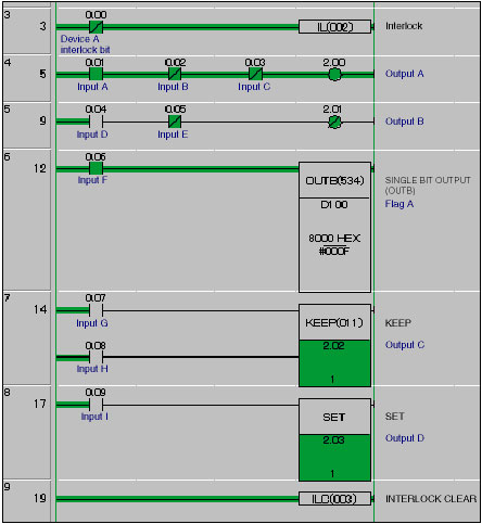
Refer to Figure 2.
*The execution condition for the IL instruction turns OFF.
Note:Other bits in D100 will not be turned OFF even if they are used in instructions other than the OUTB instruction (e.g., MOV).
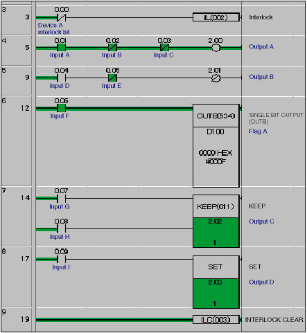
Figure 2
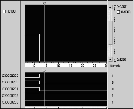
Figure 3
CIO 000000: Device interlock bit (CIO 0.00)
CIO 000200: Output A (CIO 2.00)
CIO000201: Output B (CIO 2.00)
CIO 000202: Output C (CIO 2.02)
CIO 000203: Output D (CIO 2.03)
When the device interlock bit (CIO 0.00) turns ON, outputs A and B (CIO 2.00 and CIO 2.01) turn OFF, and outputs C and D (CIO 2.02 and CIO 2.03) stay ON. D100 changes from 8000 to 0000 hex.
Note:If there are outputs that you do not want to turn OFF when the interlock is enabled in the same program block, use the KEEP instruction or SET/RESET instructions, as mentioned before.
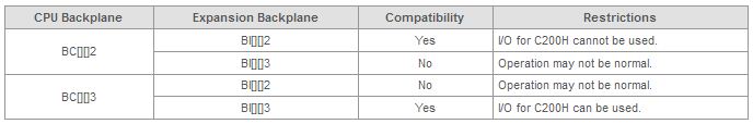
In CS1-series Programmable Controllers, can CS1W-BI[][]3 Expansion Backplane be connected to CS1W-BC[][]2 CPU Backplane? Can CS1W-BI[][]2 Expansion Backplane be connected to CS1W -BC[][]3 CPU Backplane?
No, the compatible Expansion Backplane for CS1W-BC[][]2 CPU Backplane is CS1W-BI[][]2. C200H Programmable Controllers Units cannot be mounted to CS1W-BI[][]3 Expansion Backplane. When using CS1W-BC[][]3 CPU Backplane, CS1W-BI[][]3 Expansion Backplane can be used. CS1W-BI[][]2 Expansion Backplane cannot be used.
As explained above, there are specific Expansion Backplanes that are compatible each type of CPU Backplane. If you need to mount C200H Units, you will need to use the proper combination of Backplanes.
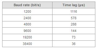
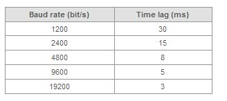
When I send and receive data with protocol macros, occasionally the data header is not received properly. Why?
If the device that you are connected to using protocol macros has a fast processing time (the time the data is received until the time the data is returned), the protocol macro may not be able to receive all of the data.
When using protocol macros, some time is necessary after sending data from the Programmable Controllers before the Programmable Controllers will be able to receive data.
Refer to the following data; the values are guidelines.
What is the .opt file that is created with the .cxp file whenever I save a project?
The .opt file stores the operating environment settings of CX-Programmer FA Integrated Tool Package. It is automatically created and saved when the project file is saved.
The .opt file saves the location and size of every window, and the symbols registered in the Watch Window while using CX-Programmer.
Deleting the .opt file will not affect the program, but the settings stored in the file will be reset to their defaults.
What is the difference between the binary and BCD forms of math instructions?
When using CX-Programmer FA Integrated Tool Package, as shown in the ladder program in Figure 1, both BINARY ADD instructions and BCD ADD instructions can be input and displayed in decimal form. The data conversion function of CX-Programmer makes this possible. You can see by looking at the internal code in the Watch Window in Figure 1 or the numeral data in Figure 2, that the internal code processed by the CPU Unit is actually binary.
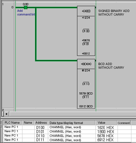
Programming: CS1/CJ1-series Programmable Controller
Figure1. Ladder Program and Watch Window
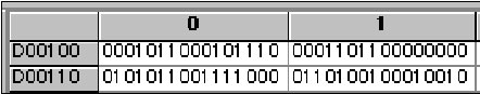
Figure2. DM Area Monitor Display for Programmable Controller Memory (Binary Mode)
Choosing an Instruction: Checkpoint 1
As previously described, the internal code for the instructions is either binary or BCD format. The value ranges for the instructions are shown in Table 1.
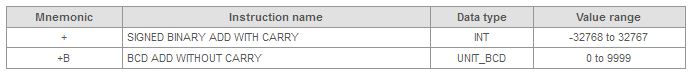
Table 1
As shown in Table 1, the difference between the "+" instruction and the +B instruction is whether the values are signed or unsigned. It can also be seen that the "+" instruction can handle a range of values 3.27 times that of the +B instruction even when the value range is limited to positive numbers. This difference in the range of values that can be handled is an important factor when selecting math instructions.
Choosing an Instruction: Checkpoint 2
Should binary or BCD format be selected? One more important point to be considered when selecting the instruction is the form of the numeric inputs for the math instruction. Table 2 shows a list of common I/O signals used by Programmable Controllers and the main code (BCD or binary) that would be used for math processing.
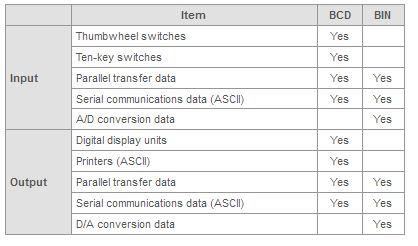
Table2. I/O Signals for Programmable Controllers
To summarize the above, the two checkpoints for math instruction selection are as follows:
Here we will give some examples of how to decide math instructions using checkpoints 1 and 2.
An internal offset value is added to a 4-digit BCD input value from a thumbwheel switch, and the result is output as a 4-digit BCD value to a digital display unit.
A 12-bit binary value from an A/D conversion unit is divided by an internal variable, and a 12-bit binary value is output to a D/A conversion unit after scaling.
When there are multiple input parameters, depending on the input device and communications control specifications, BCD data and binary data may both exist. When this occurs consider the following two questions as a general guide to select the math instruction:
After the instruction has been decided, other data in other forms will be converted into binary or BCD using the binary or BCD conversation instructions.
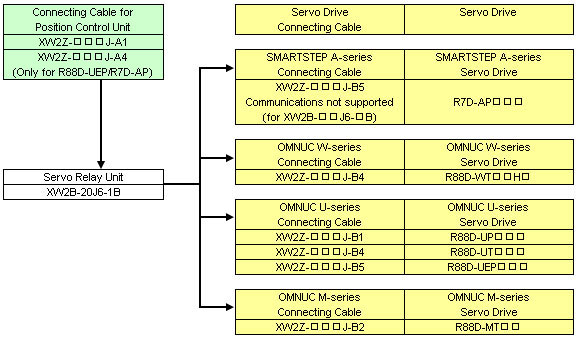
What combinations of connecting cables and Servo Relay Units are required to connect C200H-NC112 Position Control Units a Servo Drive?
Refer to the following diagram.
The address does not update correctly with IR1 in a program using the index register as shown in Figure 1. Why?
Before explaining the problems with the ladder program, we will explain the system operation specifications.
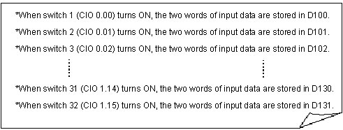
*When one of the pushbutton switches from 1 to 32 is pressed, the two words of input data (4-digit BCD data) will be stored in D100 to D131 as shown in the following example.
Programming: CS1/CJ1-series Programmable Controllers
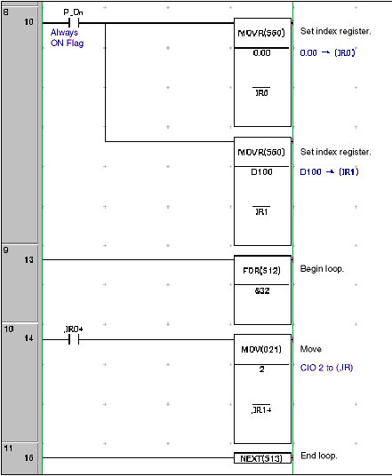
Figure 1
To get to the point, there is a problem in the usage of the auto increment option/,IR1+ in --[MOV 2,IR1+] on rung number 10 of the ladder program.
,IR[]+: The contents of IR[] will be incremented by 1 immediately after accessing the contents of the address that IR[] points to.
The ladder program in Figure 1 works like this. Immediately after the -- [MOV 2 ,IR+1] instruction on rung 10 is executed, the address in IR[] is incremented by 1. In this program, when the --| |--,IR0+ input condition is OFF, the MOV instruction will not be executed. Therefore the auto-increment process will also not be executed. This is the reason why the address update process using IR1 does not function properly.
Note:This problem will not occur with instructions that are executed each scan regardless of the execution condition, such as with --||-- ,IR0+ or with -- (,IR[]+) OUT (which does not appear here).
Programming: CS1/CJ1-series Programmable Controllers
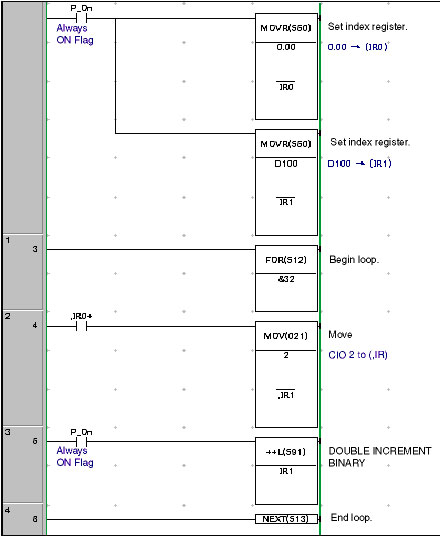
Figure 2
DOUBLE INCREMENT BINARY instruction. Increments the 8-digit hexadecimal content of two words of data by 1.
*Here, the address (32 bits) stored in IR1 is incremented by 1.
The address does not update correctly with IR1 in a program using the index register as shown in Figure 1. Why?
Before explaining the problems with the ladder program, we will explain the system operation specifications.
*When one of the pushbutton switches from 1 to 32 is pressed, the two words of input data (4-digit BCD data) will be stored in D100 to D131 as shown in the following example.
Programming: CS1/CJ1-series Programmable Controllers
Figure 1
To get to the point, there is a problem in the usage of the auto increment option/,IR1+ in --[MOV 2,IR1+] on rung number 10 of the ladder program.
,IR[]+: The contents of IR[] will be incremented by 1 immediately after accessing the contents of the address that IR[] points to.
The ladder program in Figure 1 works like this. Immediately after the -- [MOV 2 ,IR+1] instruction on rung 10 is executed, the address in IR[] is incremented by 1. In this program, when the --| |--,IR0+ input condition is OFF, the MOV instruction will not be executed. Therefore the auto-increment process will also not be executed. This is the reason why the address update process using IR1 does not function properly.
Note:This problem will not occur with instructions that are executed each scan regardless of the execution condition, such as with --||-- ,IR0+ or with -- (,IR[]+) OUT (which does not appear here).
Programming: CS1/CJ1-series Programmable Controllers
Figure 2
DOUBLE INCREMENT BINARY instruction. Increments the 8-digit hexadecimal content of two words of data by 1.
*Here, the address (32 bits) stored in IR1 is incremented by 1.
How should I handle programs that have BCD subtraction operations that result in a negative number?
When the result of a BCD arithmetic operation is a negative number, the operation result will be output as the 10's complement (see Additional Information, below), and the Carry Flag will be turned ON. As shown in Figure 1, immediately after executing the BCD SUBTRACTION WITHOUT CARRY (-B) instruction, the status of the Carry Flag (CY) (ON or OFF) is checked.
The execution result (D202) of the BCD SUBTRACTION WITHOUT CARRY (-B) instruction is handled as an absolute value without any further manipulation.
In this case, the sign bit (CIO 2.00) turned OFF to indicate a positive number.
Subtract the execution result (D202: 10's compliment) of the BCD SUBTRACTION WITHOUT CARRY (-B) instruction from 0 to convert it to the actual value, and store it in D202.
In this case, the sign bit (CIO 2.00) is turned ON to indicate a negative number.
*[-B #0 D202 D202] in Figure 1 subtracts the complement from 0000, and stores the result in D202.
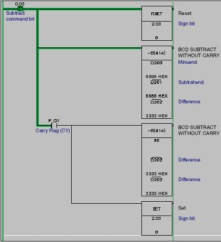
Programming: CS1/CJ1-series Programmable Controllers
Figure 1
Operation
The result of the first -B instruction is, 9,999 (D200) - 6,666 (D201) = 3333 (D202) and the Carry Flag (CY) is turned OFF. For this reason, the second -B instruction will not be executed, and the operation result is 3,333 is handled as an absolute value without any further manipulation. In this case, the sign bit (CIO 2.00) is turned OFF to indicate a positive number.
Word operands and/or constants are subtracted as 4-digit BCD values.
This flag is turned ON if there is a carry in the result of the subtraction.
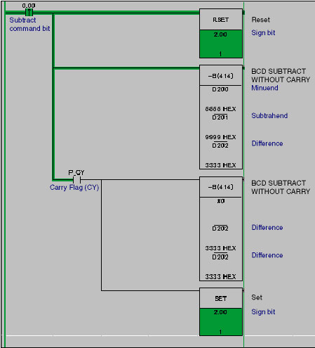
Figure 2
Operation
The result of the first -B instruction execution is, 6,666 (D200) - 9,999 (D201) = 6667 (the ten's compliment of 3,333 (D202)) and the Carry Flag (CY) is turned ON. The second -B instruction will be executed, and the complement of 6,667 is converted to the true value (3,333) and stored in D202. In this case, the sign bit (CIO 2.00) is turned ON to indicate a negative number.
Can C200H-LK201-V1 Host Link Unit be used with CS1-series Programmable Controllers?
No, C200H-LK201-V1 cannot be used with a CS1-series.
C200H Units that use the CPU bus or C200H Host Link Units cannot be used with CS1-series.
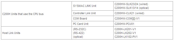
*Use CS1-series products for SYSMAC LINK, Controller Link, and COM Boards, and use Serial Communications Board or Serial Communications Unit instead of Host Link Unit.
My 8-second ON-delay timer program that uses a TIM instruction does not run properly. What is the problem?
The Problem Ladder Program
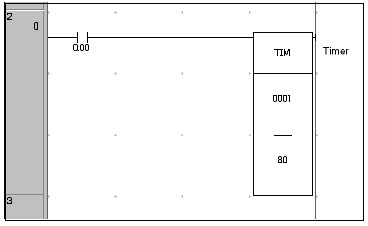
Figure 1
TIM instruction in diagram 1 has a timer setting of 80. To set an 8-second timer, this value must be changed to "#0080" (8.0 seconds).
If the timer setting value is set to 80, then the contents of CIO 80 when TIM0001 is executed will be used as the set time.
How can I connect a C200H Programmable Controller's CPU Unit with an IBM PC/AT or compatible computer?
The C200H CPU Unit and the computer cannot be connected using only a cable. An interface is always necessary. In either case, the Host Link communications mode is used.
Can individual tasks be protected on the CS1/CJ1-series Programmable Controllers?
Individual tasks can be protected when using a CS1/CJ1-series CPU Unit with unit Ver.2.0 or later and withCX-Programmer FA Integrated Tool Package Ver.4.0 or higher.
Single or multiple tasks (programs) can be password protected, preventing them from being read or modified, which makes it possible to prevent knowledge from being leaked about a specific task.
When using a Programmable Controller with unit version earlier than 2.0 or aCX-Programmer version lower than 4.0, individual tasks cannot be protected, so the entire program must be protected instead.
How do duplicated outputs work in a step program area?
If the same bit is output twice from the same program, you will get the duplicated output warning regardless, but as long as the same bit is not output twice from the same step, the output from the active step will be executed correctly.
*"One step" refers to the ladder diagram area from one step instruction to the next step instruction.
How can I manually determine internal connections between COM terminals for Programmable Controller I/O Unit?
The "number of circuits" given in the I/O Unit specifications is the same as the number of commons. Refer to C200HX/HG/HE Operation Manual and CS1 Series Programmable Controller Operation Manual.
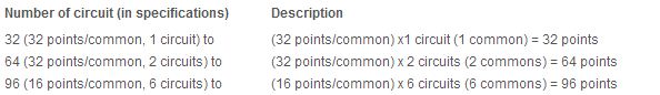
For information on specific common terminals wiring and configuration, refer to the terminal connection diagram in the same manuals.
What are push-on and push-off alternating bits?
The ladder program and data trace results are as follows:
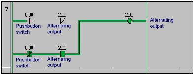
Programming: CS1/CJ1-series Programmable Controllers
Figure 1
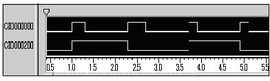
Figure 2
CIO000000: Pushbutton switch (CIO 0.00)
CIO000200: Alternating output (CIO 2.00)
What is the difference between a program task and program section when using CX-Programmer FA Integrated Tool Package with CS1/CJ1-series Programmable Controllers?
Task programming is a feature of CS1/CJ1-series. Section division is a function of CX-Programmer. Therefore, Task programming cannot be done with C200H Programmable Controller or CQM1H Programmable Controller, but by using CX-Programmer, one program can be divided up into multiple sections even when using C200H or CQM1H.
A specific example follows:
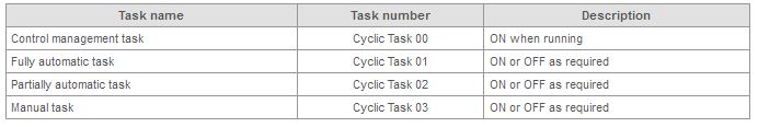
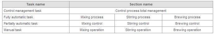
A task is the smallest executable program unit.
For example, take the case of soft drink purification manufacturing. The process has three operating modes: fully automatic, partially automatic, and manual. And, each perating mode has the three processes: the mixing process, the stirring process, and the brewing process. First, the three operating modes are divided into three separate program tasks. The reason for dividing the operating modes into separate tasks is that only one of the three tasks will be selected and run. Dividing the modes into tasks allows the other two tasks to remain stopped, thereby reducing the CPU Unit cycle time.
Step I: Task Programming Example
A specific example follows:
Using program sections makes the ladder diagram more like a segmented picture story rather than once continuous novel without chapters. Continuing with the previous mentioned soft drink example, the three processes that exist in each perating mode, the mixing process, the stirring process, and the brewing process, can each be divided into an separate program section. The reason for dividing them is that it increases the readability of the ladder programming windows.
*By clicking on the desired section name in the project tree, the requested ladder programming window will be immediately displayed.
Step II: Program Section Example
Reduces CPU Unit cycle time.
Increases the readability of the ladder programming windows.
Can I program flickering back-and-forth between two outputs when a switch is ON?
The following are the time chart and ladder programming for the operation specifications.
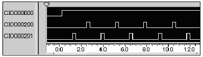
Figure 1
CIO 000000: Pushbutton switch (CIO 0.00)
CIO 000200: Alternating output A (CIO 2.00)
CIO 000201: Alternating output B (CIO 2.01)
After turning ON the pushbutton switch (CIO 0.00), the two outputs (CIO 2.00 and CIO 2.01) will alternate turning ON at intervals of T1 seconds, and remain ON for T2 seconds.
Flicker Programming
Programming: CS1/CJ1-series Programmable Controllers
Figure 2
Output Switching Program
Programming: CS1/CJ1-series
Figure 3
What is the difference between a Holding Area bit and a keep bit or a KEEP instruction?
With a SYSMAC Programmable Controllers, a Holding Area bit is a type of bit. There is no such bit as a keep bit. The correct term is the operand bit for a KEEP instruction. First, let's look at the KEEP instruction.
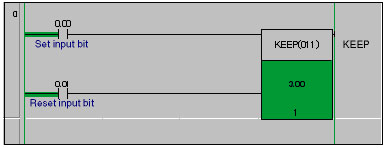
Figure 1
In Figure 1, when the set input bit (CIO 0.00) is input as a pulse signal as shown in Figure 2, the output bit (CIO 3.00) specified for the operand of the KEEP instruction will remain ON until reset input bit (CIO 0.01) turns ON. By using the KEEP instruction in this way, even after the input signal turns OFF, the output bit status can be preserved in the state it was before the input signal turned OFF.
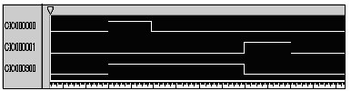
Figure 2
CIO000000: Set input bit (CIO 0.00)
CIO000001: Reset input bit (CIO 0.01)
CIO000300: Output bit (CIO 3.00)
What happens if there is a power interruption while the output bit (CIO 3.00) shown in the time chart in Figure 2 is ON? If this happens, all of the output bits will be reset when power resumes. If you want to preserve the ON or OFF status for a bit during a momentary or extended power interruption, you can use a Holding Area bit, as shown in Figure 3 (H3.00), as the bit controlled by the KEEP instruction.
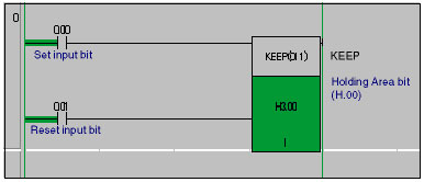
Figure 3
What should be connected to the NC terminals shown in I/O Unit terminal connection diagrams?
NC is an abbreviation for "No Connection," and means that the terminal does not have an internal connection (unused terminal). Therefore, nothing should be connected to these terminals.
Can the same DM address be used for the first and third, or second and third operand in a math instruction?
Yes. As shown in Figure 1, in a differentiated program where processing is completed with a single scan by turning ON the add command bit (CIO 0.00), there is no problem if the first (or second) operand are the same as the third operand, but after processing, the augend data stored in D100 will be deleted. For easy debugging or software maintenance, it is recommended to use a different DM Area address for the third operand.
Programming: CS1/CJ1-series Programmable Controllers
Figure 1
Initially, the value 123 (BCD) is stored in D100, but when add command bit (CIO 0.00) turns ON, the addition process given below is executing in a single scan, and the value stored in D100 will be changed from 123 to 246.
123 (D100) + 123 (constant) = 246 (D100)
Note:The instruction in Figure 1 will execute each cycle. So when you want to perform the operation A + B = C in realtime when the add command bit (CIO 0.00) is turned ON, the DM address of C must be different from that of A and B. If the same address is used, the result data will be updated as many times as the instruction is scanned causing an incorrect value to be stored in the third operand.
When I use the CX-Programmer FA Integrated Tool Package to write a differentiated instruction to CQM1H Programmable Controllers, it results in an error. Why?
As shown in diagram 1, only the CS/CJ-series CPU Units and CVM1/CV-series Programmable Controllers CPU Units can accept the differentiation option with input commands. With other models, use DIFU/DIFD, as shown in diagram 2.
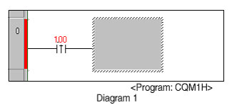
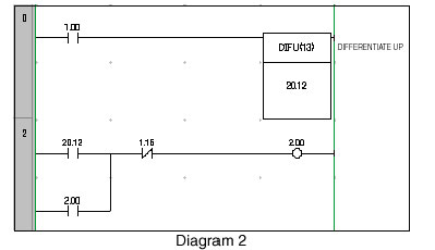
How are Memory Cards usually used with CS1/CJ1 Programmable Controllers?
The main applications of Memory Cards are as follows:
Also, the Memory Card can be removed even when power is being supplied to the CPU Unit, so data can be exchanged with personal computers or spreadsheet software while the Programmable Controllers are operating.
When monitoring a ladder diagram, sometimes the output does not turn ON even though the input condition is ON, or the output turns ON even though the input condition is OFF. What is the reason for this?
A ladder program in which the same output bit is controlled by two different instructions can cause this type of problem. Even if the input condition is ON for one instruction, the bit may have been turned OFF by another instruction somewhere else in the program. Also, if the OUT NOT instruction is used, the status of the input condition and the output bit will be reversed causing the same thing (though in this case the operation is normal).
The way output bits are displayed in CX-Programmer FA Integrated Tool Package depends somewhat on the version, but versions higher than 2.1 display input conditions in the same was as the SYSMAC Support Software (SSS).
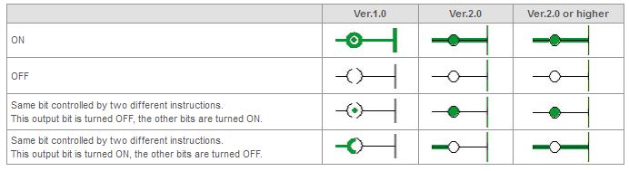
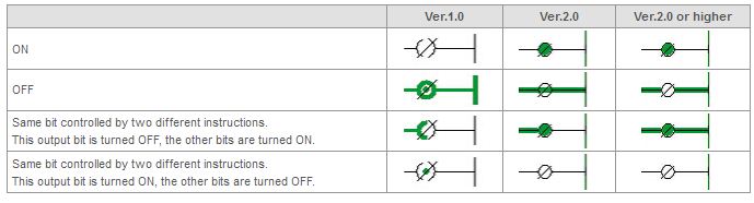
What does it mean when the "I" or "Q" is displayed in front of a bit address in a ladder program in CX-Programmer FA Integrated Tool Package?
CX-Programmer Ver.2.0 or higher displays "I:" and "Q:" in front of addresses in a ladder diagram to help you differentiate between inputs and outputs when reading the ladder diagram.
Note:Programmable Controllers that do not have I/O tables (i.e., CQM1H and CPM2A) do not have this feature.
When an address used in a ladder programoperand is an I/O bit, and the address is allocated to a Basic I/O Unit or to a High-density I/O Unit classified as a Special I/O Unit in the I/O tables, then "I:" will be automatically added to in front of the address for real inputs, and "Q:" will be added to the front of the address for real outputs.
In CX-Programmer Ver.3.0 or higher, the "I:" and "Q:" in front of the addresses that are used to differentiate between inputs and outputs can be changed to "X:" and "Y:". The setting can be changed on the Ladder Diagram Tab Page (Tools - Options - Ladder Diagram).
Are there any cables available to connect the Programmable Controller (PLC) or the Programmable Terminal (PT) to a personal computer's USB port?
Yes. Use the D-sub to USB-serial conversion cable.
This cable can connect the Programmable Controller "SYSMAC", Programmable Terminal "NT/NS Series", or Programmable Relay "ZEN" to a personal computer's USB port.
Software applications using the CX-Server or Fins Gateway to communicate with the Programmable Controller
The following software applications are also compatible.
*There are Communications (COM) port limitations with the NT Support Tool.
The following OMRON Programmable controllers, Programmable Terminals and Programmable Relays which are supported by the compatible software applications
* "Windows" is a registered trademark of Microsoft Corporation.
Can CS1/CJ1-series Serial Communication Units use non-procedural communications?
Yes, the latest Serial Communication Units can use non-procedural communications.
The TXDU and RXDU instructions for non-procedural communications can be used with CS1/CJ1-series Serial Communications Units with unit Ver.1.2 or later. In this case, the CPU Unit must be unit Ver.3.0 or later.
The TXDU and RXDU instructions for non-procedural communications can be used with CS1-series Serial Communications Boards with unit Ver.1.2 or later. The unit version of the CPU Unit is not a factor.
In previous configurations, non-procedural communications were only possible using the built-in RS-232C port on a CPU Unit using the TXD and RXD commands.
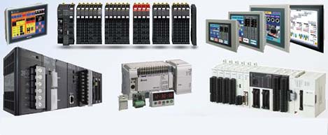 Automation Systems
  Motion & Power Solutions
  Safety, Vision and IDENT
  Sensing Solutions
  Control Components
  Switching & Accessories
  Switchgear and Trolley Systems
  Process Weighing
  LED Lighting
  Omron
Omron
 Mitsubishi
 Delta
Delta
 Autonics
 Inno
Inno
 Honeywell
 Novotechnik
 Orientalmotor
 Microscan
 IPA
IPA
 Technomech
 Intech
 IOT & Traceability
 Project & Panel Engg.
 Application Case Studies
 Solutions by Industry
 Solutions by Process
 Solutions by Product
 Corporate Information
 Company Profile
 Quality Policy
 Mission Statement
 Chairman's Message
 Intech Group Companies
