Frequently asked questions and answers for Solid-state Relays - Industrial Automation
What is the soft-start function?
The soft-start function is a function that gradually increases Solid-state Relays output using phase control until it reaches 100%. It is applicable to Solid-state Relays with AC outputs and allows a smooth startup by suppressing the starting current. This function is effective for applications with motors and halogen lamps.
What is the difference between phototriac and photocoupler isolation for the G3NA Solid-state Relay?
The applicable output load voltage range is different.
Solid-state Relays with a zero cross function using a photocoupler can operate with a small input current because they have very good coupler transmission efficiency.
Photocoupler Input Current < Phototriac Input Current
The input current for a phototriac is greater than that for a photocoupler, but that doesn't necessarily mean it must be a selection criteria for the type of Solid-state Relays. Other parameters can be used as a basis for selection.
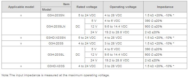
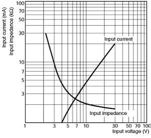
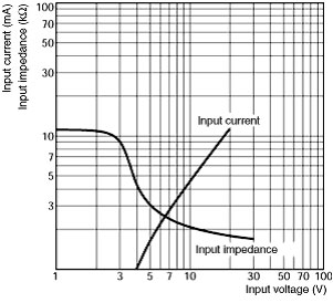
Does the input current change for Solid-state Relays with a wide rated input voltage?
In Solid-state Relays which have wide input voltages (such as G3F and G3H), the input impedance depends on the input voltage and changes in the input current. For semiconductor-driven Solid-state Relays, changes in voltage can cause malfunctions in the semiconductor, so be sure to check the actual device before usage.
This is not the case for Solid-state Relays with DC inputs that use a constant current input method (such as G3NA and G3PA).
Why is a switching time lag necessary for the forward and reverse operation of a three-phase motor?
The forward and reverse operation of a three-phase motor is conducted by switching two phases. If the Solid-state Relays for forward and reverse operation are switched ON simultaneously, a phase short-circuit will result through the two Solid-state Relays, causing the Solid-state Relays to breakdown.
Also if the forward and reverse Solid-state Relays are switched over immediately, both Solid-state Relays could become ON at the same time because the Solid-state Relays reset time varies by up to a half cycle, which would cause the Solid-state Relays to breakdown.
When an Solid-state Relays is turned OFF, counter-electromotive force may be generated from the motor and cause a malfunction. If this occurs, it is necessary to increase the time lag between switching.
Make sure that there is a time lag of at least 100 ms.
G3J Simple Solid State Contactors with G36 Reversible Units
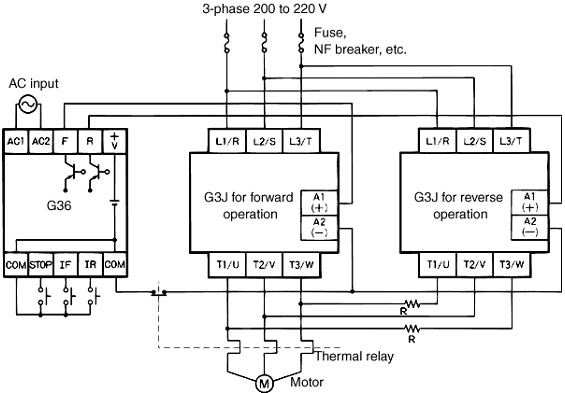
To prevent short-circuits, insert the protective resistance R into the circuit. The value of R can be calculated using the following equation.
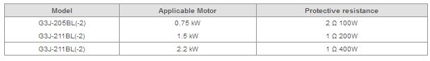
G3J-205BL
For example, G3J-205BL withstands an inrush current of 150 Apeak. Therefore R > 200 V x √2/150 A = 1.9 Ω
Considering the circuit current and ON time, insert the protective resistance into the side that reduces the current consumption.
Obtain the consumption power of the resistance from the following.
P = I2R × Safety factor
(I = Load current, R = Protection resistance, Safety factor = 4)
Note:
1.Make sure that safety devices, such as fuses or NF breakers, are used.
2.G36 can be used only with G3J with a rated operating DC voltage.
3.G36 can be use by shorting the COM and IF (IR or STOP) terminals.
4.To prevent short-circuits, insert the protective resistance R.
5.Two of G3J-S and G3J-T cannot be used together for forward and reverse operation.
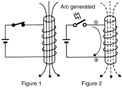
What is counter-electromotive force (surge)?
Counter-electromotive force is the voltage that arises in the reverse direction when the switch is set to OFF with an inductive load using a coil. As shown in Figure 1, flux is generated when voltage is applied to the coil.
When the switch is set to OFF again, there is no more flux, but the coil's self-induction action causes counter-electromotive force to be generated in the direction where flux remains. A very high voltage is generated because the switch is already open and there is no place for the power arising from the coil to escape to.
Counter-electromotive force may cause contact wear and element damage. Use caution when using coil loads. As shown in Figure 2, both the power supply voltage and the counter-electromotive force will be applied to the open switch.
We think a Solid-state Relay (SSR) is faulty. Can a voltage tester be used to check an SSR to see if current is flowing?
No, that is not possible.
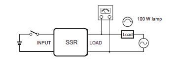
The voltage and current in the tester's internal circuits are too low to check the operation of the semiconductor element in the SSR (a triac or thyristor). The SSR can be tested as described below if a load is connected.
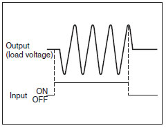
Connect a load and power supply, and check the voltage of the load terminals with the input ON and OFF. The output voltage will be close to the load power supply voltage with the SSR turned OFF. The voltage will drop to approximately 1 V with the SSR turned ON. This is more clearly checked if the dummy load is a lamp with an output of about 100 W.
(However, the capacity of the lamp must be within the rated range of the SSR.)
What kind of applications can Power MOS FET Relays be used for?
1. Applications where it is not known whether the load connected to the relay is DC or AC.
Example: Warning output for a robot controller
2. Applications with high-frequency switching of loads, such as for solenoid valves with internally, fully rectified waves, where another type of relay (e.g., G2R General-purpose Relays) would need to be replaced frequently.
Power MOS FET Relays have a longer lifetime than other Relays and so the replacement frequency is lower. The terminals of G3RZ Power MOS FET Relays are compatible with those of the G2R-1A-S and so these models can be easily exchanged.
Note:Be sure to confirm the input voltage, polarity, and output capacity.
3. Applications with high-voltage DC loads.
To switch a 100-VDC, 1-A load with M2XP General-purpose Relays or equivalent is required. With G3RZ Power MOS FET Relays, however, switching is possible with this size of relay.
4. Applications where otherwise a Solid-state Relays would be used with a bleeder resistance.
The leakage current for Power MOS FET Relays is very small (10 μA max.) and so a bleeder resistance is not required.
What should be done about surge-absorbing circuits for AC-load Solid-state Relays?
Measures against AC Switching Solid-state Relay Output Noise Surges
1. The Solid-state Relay has a built-in snubber circuit to smooth out a sudden rise in voltage. If there is a large voltage surge in the output-side AC power supply, the snubber circuit will not be sufficient to suppress the surge, and overvoltage will damage the output elements.
2. The following models have a built-in surge-absorbing varistor: G3NA, G3S, G3PA, G3PB, G3NE, G3J, G3NH, G9H, G3DZ (some models), G3RZ, G3FM
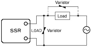
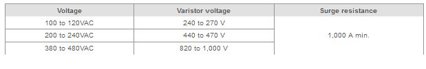
3. Be sure to take measures against surge when switching an inductive load with an Solid-state Relay that does not have a built-in surge-absorbing element. (Refer to the following figure.)
Note:A separate varistor with a surge resistance higher than the built-in varistor must be mounted externally if influence is possible from noise that is not completely absorbed by the built-in varistor (surge resistance: 700 to 1000 A).
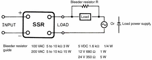
What is bleeder resistance?
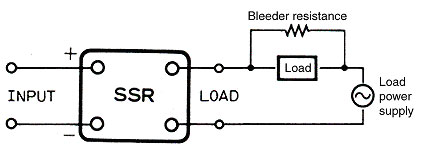
Bleeder resistance is resistance connected in parallel with the load so that the load current appears to increase in order to correctly switch microloads.
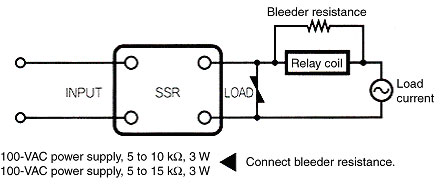
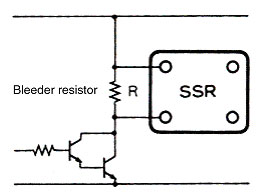
Why do Solid-state Relay load Relays sometimes hum?
Leakage current flows when the Solid-state Relay input is OFF. If a small Relay is driven, this Leakage current may cause the Relay coil to become slightly energized, which results in a humming sound being produced.
Insert bleeder resistance in parallel with the Relay coil to eliminate any humming. The same effect as bleeder resistance can also be obtained by connecting multiple Relay coils in parallel or connecting the Relay coil in parallel with another load.
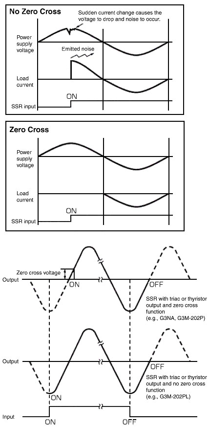
What is the zero cross function?
The zero cross function causes the Relay to turn ON when the AC load power supply approaches 0 V to suppress noise generated when the load current rises suddenly.
There are two types of noise: noise on power lines and noise emitted into open spaces. The zero cross function is effective against both types of noise.
A very large inrush current flows when lamps and similar equipment are turned ON, but the zero cross function causes the load current to always flow from a point near zero so that inrush current can be suppressed more compared to Solid-state Relays that do not have the zero cross function.
Ideally, the function turns ON near 0 V, but restrictions in the circuit configuration cause it to operate within the range of 0 V ±20 V. This voltage is called zero cross voltage.
What is a snubber circuit?
A snubber circuit is a circuit consisting of a resistor (R) and a capacitor (C) that prevents faulty ignition from occurring in the Solid-state Relay triac by suppressing a sudden rise in the voltage applied to the triac.
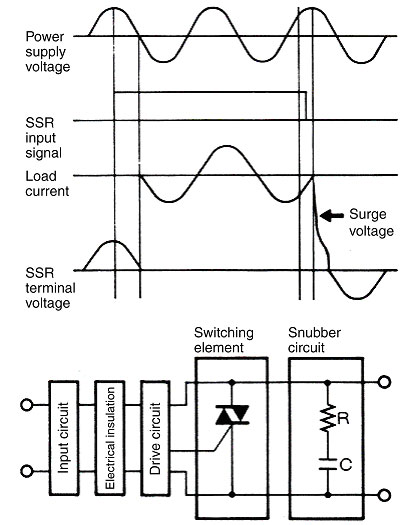
Switching an inductive load, such as a motor, using an Solid-state Relay with triac or thyristor output causes the voltage to suddenly change (voltage transience) when the load is turned ON or OFF and results in incorrect operation (faulty ignition).
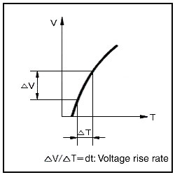
The characteristics for voltage transience with a triac or thyristor are expressed as dv/dt.
The maximum value at which voltage transience will cause switching from OFF to ON is called the critical rate of OFF-state voltage (static dv/dt). For a triac, the maximum value at which voltage transience will not cause switching from ON to OFF is called commutation dv/dt.
The snubber circuit works to suppress surges, but the output semiconductor elements may be damaged if a large voltage surge is applied. Therefore, measures against surge are required in addition to the snubber circuit if an Solid-state Relay that does not have a built-in surge-absorbing element (varistor) is used with an inductive load.
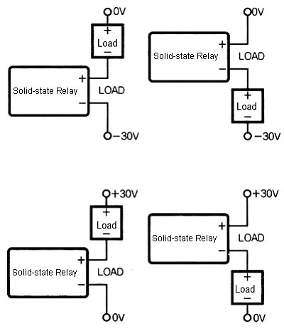
Can Solid-state Relays for DC loads be connected to a negative power supply?
Connections can be made in any of the configurations shown in the following diagrams.
If the load has positive and negative terminals, match the polarity of Solid-state Relays when connecting it.
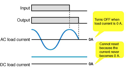
Can a DC load be used with Solid-state Relays for AC loads?
No, it cannot be used. The element characteristics of Solid-state Relays will not allow it to reset if a DC load is used.
Solid-state Relays for AC load switching use thyristors and triacs as output elements. By turning Solid-state Relays input ON, the output can be turned ON, but simply turning the input OFF doesn't mean that the output will be turned OFF. This is because Solid-state Relays have a characteristic that it stays turned ON until the load current becomes zero regardless of the absence of input signals into Solid-state Relays.
The DC current will never become zero, therefore it will not be reset.
The Solid-state Relay (SSR) is too hot to touch. Does it have any trouble?
Although when the maximum current flows in the rated range, the temperature of the SSR reaches around 80 to 100 degrees, it is not abnormal.
However, pay careful attention to the heat loss. In general, when the ambient temperature is high, the value of switchable load currents decreases.
Switching elements in the SSR such as TRIAC, Thyristor and power transistor produce heat by having residual voltage (voltage lost inside a semiconductor when it turns ON).
Why is the minimum load current for most Solid-state Relays specified at 0.1 A?
For triac and thyristor output elements to stay ON, a small amount of current flow (called the holding current) is required. Considering the added effect of the ambient operating temperature, the output element may not be able to stay ON if the load current is less than 0.1 A. This may cause oscillations to appear in the output, or for it to not turn ON at all.
Solid-state Relays typically have less than 10 mA or leakage current at 200 V. To prevent the leakage current from causing load reset errors, the reset current is estimated to be at least 10% of the rated current, and the minimum load current is specified at 0.1 A.
For example, if a load with a rated current of 50 mA is used and the OFF leakage current is 10 mA, the load current would be 20% of the rated load. Depending on the load, this may cause a reset error.
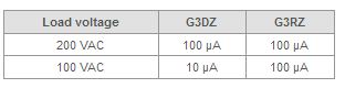
Power MOS FET Solid-state Relays do not require a holding current, and feature small leakage currents. The minimum load current required for Power MOS FET Solid-state Relays to operate normally at 200 VAC is 100 µA.
Is it possible to connect Solid-state Relays in parallel?
Yes, it is.
Solid-state Relays are connected in parallel mainly to prevent open circuit failures.
Usually, only one of the Solid-state Relays is turned ON, keeping the other Solid-state Relay in the OFF state, due to the difference in output ON voltage drop between the Solid-state Relays. Therefore, do not connect two or more Solid-state Relays in parallel to drive a load exceeding the capacity of each Solid-state Relay. Otherwise, Solid-state Relays may fail to operate.
It is not possible to increase the load current by connecting the Solid-state Relays in parallel.
However, if an ON-state Solid-state Relay in operation is open, the other Solid-state Relay will turn ON when the voltage is applied, thus maintaining the switching operation of the load.
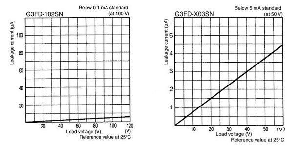
What is the relationship between the leakage current and the load voltage?
The leakage current increases proportionally with the load voltage.
Refer to the following graphs.

What are the characteristics of a triac and thyristor?
Triacs and thyristors can switch the flow of an electricity supply. Solid-state Relays use this function to switch AC power. Solid-state Relays that switch AC power thus have the characteristics of triacs and thyristors.
They are different from power transistors or power MOS FETs, because they are semiconductor devices they cannot turn themselves OFF. They can be turned ON with a gate signal to supply current but simply turning the gate signal OFF will not stop the current. The element will remain ON until the current flow reaches zero. This is an important aspect that must be considered to ensure safety in the system design, as well as the fact that semi-conductors are susceptible to breakdown caused by short-circuits.
What should be done for a surge-absorbing circuit for DC-load Solid-state Relays?
Countermeasures against DC Switching Output Noise Surges
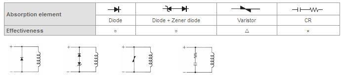
When an L load, such as a solenoid or electromagnetic valve is connected, connect a diode that prevents counter-electromotive force. If the counter-electromotive force exceeds the withstand voltage of the Solid-state Relay output element, it could result in damage to the Solid-state Relay output element.
As a countermeasure, insert the elements in Figure 1 in parallel with the load. (Refer to the following figure.)
As an absorption element, the diode is the most effective at suppressing the counter-electromotive force. The release time for the solenoid or electromagnetic valve will, however, increase. Be sure to check the circuit before use. To shorten the time, connect a Zener diode and a regular diode in series. The release time will be shortened at the same rate that the Zener voltage (Vz) of the Zener diode is increased.
Figure 1: Absorption Element Example
1.
Selecting a Diode
Withstand voltage = VRM ≥ Power supply voltage × 2
Forward current = IF ≥ Load current
2.
Selecting a Zener Diode
Zener voltage = VZ < (Solid-state Relay's connector − emitter voltage)* − (Power supply voltage + 2 V)
Zener surge reverse power = PRSM > VZ × Load current × Safety factor (2 to 3)
Note:When the Zener voltage is increased (VZ), the Zener diode capacity (PRSM) is also increased.
What are the main causes and solutions of the Solid-state Relays (SSR)'s failures?
If an inrush current exceeds the rated making current of the SSR due to the high inrush current of loads such as motors and lamps, SSR output elements are damaged.
Consider using an SSR with a higher capacity.
High reverse voltage caused by inductive loads such as valves and solenoids may have the SSR output elements damaged. Use the SSR with an element absorbing reverse voltage generated.
An external surge may suddenly damage input or output elements. A load short circuit may also cause malfunction. Design a safety circuit which will turn off the load by a contactor or a circuit breaker on the load power supply side when the SSR causes an error. It is also recommended to connect a quick-break fuse in series with the load as an over-current protection measure.
If an ambient temperature exceeds the rated value, the SSR output elements may be damaged. Install the SSR considering its heat radiation conditions such as air convection around the heat radiator.
If the SSR is used with loose screws of its output terminals or imperfect solder, abnormal heat generation while current flowing causes the SSR to burn out. Perform the proper wiring and soldering.
Are Solid-state Relays unable to switch microloads?
The minimum load currents in the following table can be switched using Solid-state Relays with Power MOS FET outputs (G3DZ/G3RZ).
Minimum Load Currents for G3DZ and G3RZ
The following applies to AC Solid-state Relays with triac or thyristor outputs and to DC Solid-state Relays with power transistor outputs.
At present, the minimum load current for most Solid-state Relays is 100 mA (50 mA at an ambient temperature of 25°C or higher) considering the degree of current (holding current) required because of problems with the load failing to reset due to leakage current and the output elements remaining ON.
Microloads below these values can be supported by connecting bleeder resistance in parallel with the load. By using MOS FETs, however, microloads can be directly switched without bleeder resistance.
Bleeder Resistance
Leakage current may cause the load to fail to reset.
There is generally no problem for most microload switching with Solid-state Relay models with a leakage current of 0.1 mA or less. Caution is required, however, for G3CN-D Solid-state Relays, G3FD Solid-state Relays, G3HD Solid-state Relays and other models with large leakage current.
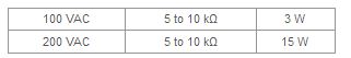
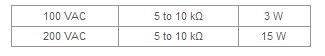
The following table provides a rough guide to bleeder resistance if reset failure occurs using the G3CN-D, G3FD, or G3HD.
Bleeder Resistance
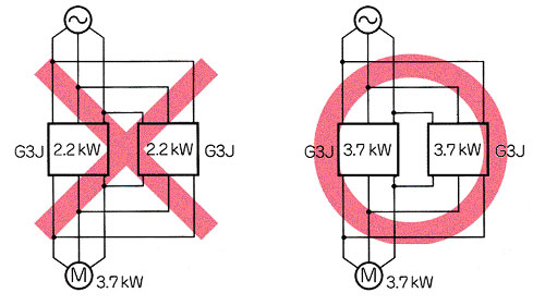
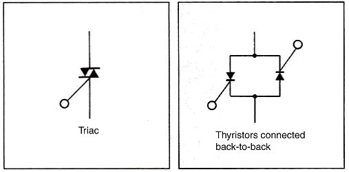
What is the difference between triacs and thyristors?
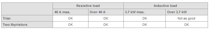
They are essentially the same in terms of resistive loads. For inductive loads, however, back-to-back thyristors are effective. Thyristors connected back-to-back or a triac can be used for Solid-state Relay switching elements.
Thyristors and the triacs differ in their characteristics to enable the elements to adjust to a rapid rise or fall.
These characteristics are expressed as dv/dt (unit: V/ μs). The dv/dt value for thyristors is greater than the value for triacs.
Triacs help downsize Solid-state Relays because they can sufficiently perform switching for motors of up to the 3.7-kW class with inductive loads, and one triac element provides functionality equivalent to two thyristors connected back-to-back.
Note:dv/dt is the rate of voltage rise.
The Solid-state Relay does not turn OFF. What is causing this and what can be done about it?
There may be separate causes for the input side and the output side. The following provides separate explanations.
1. Leakage current of the drive circuit on the input side may be causing a reset failure. Insert a bleeder resistor as a countermeasure.
Connect a bleeder resistor as in the figure above and set the bleeder resistance value so that the Solid-state Relay input voltage is 0.5 V max. when the Solid-state Relay is OFF.
2. Inductive noise may be inducing voltage on the input circuit. As a countermeasure, separate the power lines and the signal lines. Also use twisted wire or shielded wire to reduce the inductive voltage to below the Solid-state Relay reset voltage.
1.
Reset Failure due to Solid-state Relay Leakage Current
Reset Failure due to Solid-state Relay Leakage Current Even when there is no input signal to the Solid-state Relay there is a small Leakage Current (IL) from the Solid-state Relay output (LOAD). If this Leakage Current is larger than the load release current, the Solid-state Relay may fail to reset.
Connect the bleeder resistance R in parallel to increase the Solid-state Relay switching current.
Note:Microloads can be supported by using a bleeder resistor as described above. MOS FETs, however, can be used to directly switch microloads without a bleeder resistor.
2. Reset Failure Using Load with Low Power Factor
If the power factor of the load is low (guideline: cosΦ=0.4 max.), the delay in the load current phase will increase relative to the load power supply voltage phase, and a large transient voltage (dv/dt) will be applied to the Solid-state Relay when it is about to turn OFF (i.e., the load current is near zero), resulting in the possibility of the Solid-state Relay not being able to turn OFF (commutation failure).
The Solid-state Relay has a built-in CR snubber circuit to limit the rate of change in the transient voltage, but leakage current will increase if the C value is increased, and reset failure in item 1 above may occur, so the C value is set to the greatest common factor.
Therefore, if reset failure occurs because the load power factor is low, the rate of change in the transient voltage can be limited to prevent reset failure by connecting a capacitor and resistor in parallel with the Solid-state Relay load terminals.
The capacitor and resistor must be checked to match the load, but previous experience shows that a resistor of 100 Ω/1 W and a capacitor of 0.1 μF/250 VAC will prevent reset failure.
Also, as mentioned above, the leakage current will increase, so check that the reset failure in item 1 does not occur.
Is it possible to connect Solid-state Relays (SSRs) in series?
Yes, it is. SSRs are connected in series mainly to prevent short circuit failures. Each SSR connected in series shares the burden of the surge voltage. The overvoltage is divided among the SSRs, reducing the load on each.
A high operating voltage, however, cannot be applied to the SSRs connected in series. The reason is that the SSRs cannot share the burden of the load voltage due to the difference between the SSRs in operating time and reset time when the load is switched.
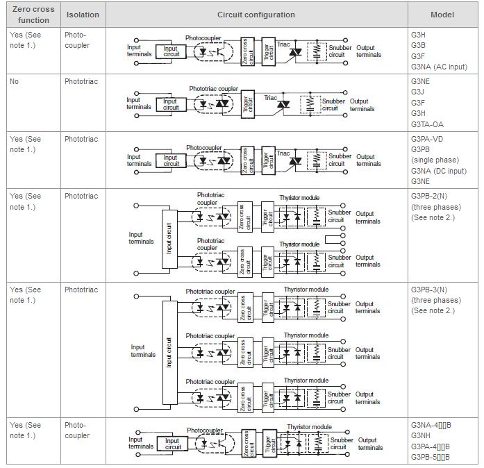
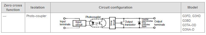
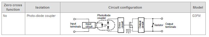
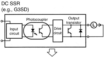
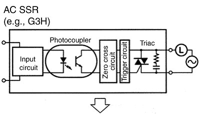
How are the internal Solid-state Relays circuits configured?
Examples of Solid-state Relays Internal Circuit Configuration
Load specifications
AC load
Load specifications
DC load
Load specifications
AC/DC load
Note 1:
The zero cross function turns ON the Solid-state Relay when the AC load voltage is 0 V or close to 0 V. Solid-state Relays with the zero cross function are effective in the following ways.
・Clicking noise when a load is turned ON is reduced.
・Effects on the power supply are reduced by suppressing inrush current with loads, such as lamps, heaters, and motors, thereby reducing inrush current protection circuits.
Note 2:
For 200-V models, use a triac on the output switching elements.
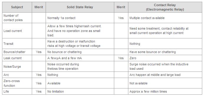
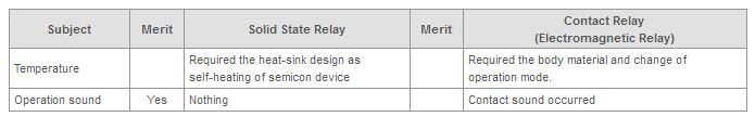
What is the difference between Solid-state Relays and Contact Relays?
Solid State Relays use semiconductors for no-contact operation. Solid-state Relays are not very different in operation from Contact Relays (Electromagnetic Relays). Solid-state Relays, however, consist of electronic parts with no mechanical contacts. Therefore, Solid-state Relays have a variety of features that Contact Relays do not incorporate.
Use both Relays in accordance with the intended use.

Are there Solid-state Relays available with NC contacts?
NC contacts cannot be implemented for Solid-state Relays with triac or thyristor outputs without a drive power supply.
To form NC contacts, the semiconductor used for output must be normally closed (NC) and a depression transistor is required.
Solid-state Relays with NC contacts using depression MOS FETs have been commercially available recently mainly for applications with small signal currents.
G3VM Solid-state Relay is available from OMRON with NC contacts.
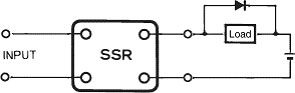
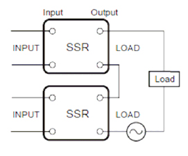
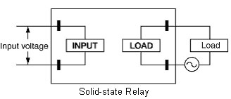
Should the load be connected to the LOAD or to the INPUT terminal?
The load must be connected to the LOAD terminal.
What is the equation for calculating the heat radiated by Solid-state Relays?
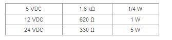
The amount of heat radiated by Solid-state Relays can be found using the following equation. Heating value P (W) = Output-ON voltage drop (V) x Carry current (A)
For example, if a load current of 8 A flows from G3NA-210B Solid-state Relays, the following heating value will be obtained. P = 1.6 V x 8 A = 12.8 W
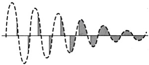
The current is unstable when the power supply is switched using an Solid-state Relay. Why is this?
Using a smoothing capacitor makes the power supply a capacitive load, but as shown in the following figure, the current output is clearly divided between times when hardly any current flows and times when the capacitor is suddenly charged.
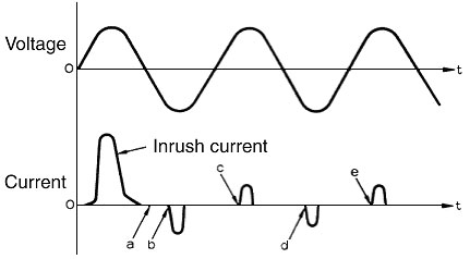
When an attempt is made to turn the Solid-state Relay ON, voltage is applied to the Solid-state Relay, and the Solid-state Relay tries to turn ON, but near point A where there is no current flow the ON status cannot be maintained, so the Solid-state Relay turns OFF and then turns ON when the charge current starts to flow at point B.
Similarly, the Solid-state Relay moves from OFF to ON at point C. If there is a delay in the Solid-state Relay turning ON at point B, the capacitor will no be sufficiently charged, and when the Solid-state Relay turns on at point C it will try to charge the amount insufficient at point B, which will result in a large current flowing. The current is unstable because this process is repeated at points D and E.
As a measure to stabilize the current, connect a bleeder resistor that constantly passes current in parallel with the power supply to keep the Solid-state Relay ON.
Bleeder Resistance
What is the difference between the input rated voltage and operating voltage for Solid-state Relays?
The voltage that serves as the standard value of an input signal voltage. The voltage must be within this range.
The permissible voltage range of an input signal voltage. The applied voltage may fluctuate within this range. Voltages outside this range cannot be used.
What is the difference between an Solid-state Relay and a power MOS FET?
There are two main differences between Solid-state Relays and power MOS FETs.
There are DC Solid-state Relays and AC Solid-state Relays.
A Power MOS FET Relay can be used with either a DC load or AC load.
The leakage current is smaller compared with an Solid-state Relay.
Leakage current causes the lamp to light dimly. A bleeder resistor is added to prevent this. The Solid-state Relay requires a snubber circuit to protect the output elements. This is the cause of Leakage current.
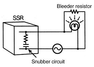
Because the leakage current is very small (e.g., 10 mA max.) the lamp does not light dimly. This is because a snubber circuit is not required to protect the output element MOS FET. A varistor is used to protect the MOS FET.
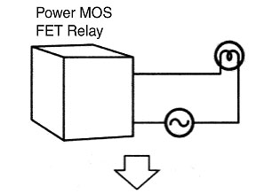
The circuit can be simplified and work reduced because a bleeder resistor is not required.
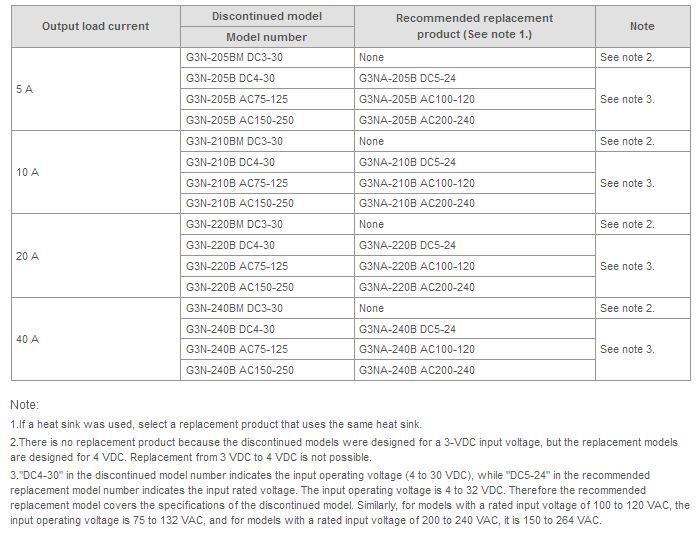
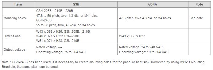
What is the recommended replacement product for G3N Solid-state Relays?
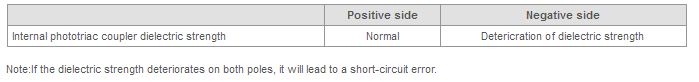
Solid-state Relays Output Short-circuit Malfunction 1: Why do the Solid-state Relays output always use half-wave operation?
The dielectric strength of one Solid-state Relay channel may have deteriorated as a result of an overvoltage to the Solid-state Relays output terminal caused by a noise surge (including high frequency noise).
Solid-state Relays Internal Circuit with Problematic Section
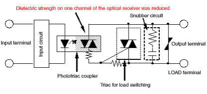
The I/O insulation element of the affected Solid-state Relays circuit may be a photocoupler or a phototriac coupler, and the load switching (output) element may be a thyristor or a triac.
Example of a Phototriac Coupler with Deteriorated Dielectric Strength on One Channel of Optical Receiver
Possible Causes
Reference Information Relating to Protection against External Noise
As protection against external noise, it is recommended that an overvoltage protection element (e.g., a varistor) is externally connected to the power supply line.
Connection Example 1
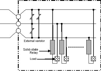
Connection Example 2
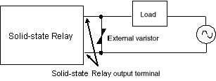
Note:Check the manufacturer's information for how to connect the overvoltage protection element.
Solid-state Relays Output Short-circuit Malfunction 2: What cause an Solid-state Relays output to short-circuit?
An overcurrent flowed through the Solid-state Relays output and damaged the output elements.
Solid-state Relays Output Open Circuit Malfunction: Why doesn't the Solid-state Relays output turn ON?
The current-limiting resistor built into the Solid-state Relays may have experienced an open circuit error caused by application of overvoltage to the Solid-state Relays output terminal due to noise surge (including high frequency noise).
Solid-state Relays Internal Circuit with Problematic Section
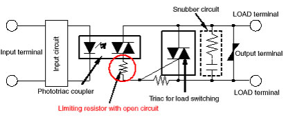
Note:Depending on the Solid-state Relays, the I/O insulation element may be a photocoupler, and the load switching (output) element may be a thyristor.
Possible Causes
Reference Information Relating to Protection against External Noise
As protection against external noise, it is recommended that an overvoltage protection element (e.g., a varistor) be externally connected to the power supply line.
Connection Example 1

Connection Example 2

Note:Check the manufacturer's information for how to connect the overvoltage protection element.
Solid-state Relays Breakdown Prevention: High Density or Gang Mounting. What is the relationship between the load current and the ambient temperature rating when using high-density or gang mounting?
The relationship between the load current and the ambient temperature rating is a characteristic of Solid-state Relays. It describes the amount of load current required for operating Solid-state Relays in relation to the ambient temperature measured at the specified ambient temperature measuring position during mounting and operation of the Solid-state Relays, including any self-generated heat.
Note:
1.It takes approximately 60 minutes for the heat generated from the Solid-state Relays to reach its saturation point.
2.Use actual summer temperatures as the ambient temperature.
Continued use of an Solid-state Relays at a level that exceeds the load current vs. ambient temperature rating will lead to the deterioration or breakdown of the Solid-state Relays.
Reducing the load current may be required for high-density or gang mounting for some Solid-state Relays.
Example: Load Current Vs. Ambient Temperature Rating for High-density or Gang-mounted G3PA-220B-VD Solid-state Relays.
For G3PA the following conditions apply when using high-density or gang mounting.
Note:The above conditions will depend on the Solid-state Relays.
The solid line in the graph shows the load current vs. Solid-state Relays ambient temperature rating for vertical-mounted G3PA-220B-VD.
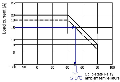
Therefore, when using high-density or gang mounting, if the ambient temperature is 50°C, the load current must be kept below 15 A.
 Automation Systems
  Motion & Power Solutions
  Safety, Vision and IDENT
  Sensing Solutions
  Control Components
  Switching & Accessories
  Switchgear and Trolley Systems
  Process Weighing
  LED Lighting
  Omron
Omron
 Mitsubishi
 Delta
Delta
 Autonics
 Inno
Inno
 Honeywell
 Novotechnik
 Orientalmotor
 Microscan
 IPA
IPA
 Technomech
 Intech
 IOT & Traceability
 Project & Panel Engg.
 Application Case Studies
 Solutions by Industry
 Solutions by Process
 Solutions by Product
 Corporate Information
 Company Profile
 Quality Policy
 Mission Statement
 Chairman's Message
 Intech Group Companies
