Before selecting an inverter, first the motor should be chosen. In selecting the motor, first calculate the load inertia for the applications, and then calculate the required capacity and torque.
Before selecting an inverter, first the motor should be chosen. In selecting the motor, first calculate the load inertia for the applications, and then calculate the required capacity and torque.
This method of calculation helps select a motor by calculating the output (W) required by the motor to maintain its regular rotations. It does not include calculation of the effect of acceleration//deceleration. Therefore, make allowance for the calculated value to select a motor. This calculation method can be applied to applications that operate constantly such as fans, conveyors, agitators etc.
This calculation method must not be applied to the following applications:


This method helps to select a motor by calculating the effective torque and maximum torque required to achieve a certain pattern of operation for the application. It selects a motor that is optimal for a particular operation pattern.
Calculate inertias of all the components with the formula for inertia calculation shown below to convert them to a motor conversion value.


Calculate the acceleration torque from the load torque calculated from both the motor shaft conversion value and the motor rotor inertia. Then Combine this acceleration torque and the load torque calculated from the friction force and the external force that are applied to the load. Now you get the required torque to operate a motor.
Acceleration Torque

Motor Shaft Conversion Load Torque (External Force/Friction)


Maximum Torque: TMAX = T1 = TA + TL

* Please make use of the Servo Motor selection software, which can calculate the motor shaft conversion inertia and effective/maximum torque, as above.
Use the formula below to calculate the motor capacity from the effective torque and the maximum torque that were obtained above.
Select the larger of the two generated values as the motor capacity.
Select a motor the capacity of which is larger than the calculated value and makes allowance for an error.
Select an inverter that can be used for the selected motor in the process of "Motor Selection".
Generally, select an inverter which fits the maximum applicable motor capacity of the selected motor.
After selecting an inverter, check if it meets with all of the following conditions. If it does not, select an inverter that has a one class larger capacity and check the feasibility again.
Motor Rated Current = Inverter Rated Output Current Maximum Time of Continuous Torque Output Time in an Application = 1 minute
* Where the inverter overload capacity is "120% of Rated Output Current for 1 minute", check it for 0.8 minute. * Where a 0 Hz sensor-less vector control is being used, or where torque must be maintained for 0 (r/min) rotation speed and where 150% of the rated torque is frequently required, use an inverter which is one rank larger than the one selected by the above method.
If the regenerative energy generated in deceleration or descent in an application is too great, the main circuit of an inverter may have an increased voltage and it may be damaged.
Because the inverter usually contains the overvoltage LAD stop function, it is not actually damaged. However, the motor stops detecting an error, making a stable and continuous operation disabled. Therefore, you must discharge the regenerative energy outside of the inverter.
A load connected to a motor has kinetic energy when rotating, and potential energy when it is located in a high position. When the motor decelerates, or when the load descends, the energy is returned to an inverter. It is known as regeneration, and the energy generated by the phenomenon is known as regenerative energy.

The following are methods to prevent the connection of braking resistance.
These methods will make the deceleration time increase, so check if it will not cause problems.
It can be a simple selecting method by using the ratio of time in which regenerative energy is produced in a normal operating pattern.
Calculate the usage ratio from the following operating pattern.

Usage Rate = t/T × 100 (% ED)
t: Deceleration Time (Regenerative Time)
T: Single Cycle Operation Time
When the usage ratio for the braking resistor selected on the previous page exceeds 10% ED, or when an extremely large braking torque is required, use the method below to calculate a regenerative energy and make your selection.


V: 200V class inverter 385 [V]
400V class inverter 760 [V]
T: Maximum Braking Torque [N·m]
Tm: Motor Rated Torque [N·m]
N: Maximum Rotation Speed [r/min]
* Calculate a braking torque using the above "Motor Capacity Selection".
Regenerative Energy is produced when the motor rotation direction and the torque direction are opposite.
Use the following formula to calculate a Regenerative Energy per cycle interval.


* Forward rotation direction is Forward for the speed, and the torque in the Forward rotation direction is Forward for the torque.
* Calculate a braking torque using the above "Motor Capacity Selection".
Select a Braking Resistor from the required braking resistance and average regenerative energy on the left.
* If a resistance that has a less then the minimum connectable value is connected on an inverter or regenerative braking resistor unit, the internal breaking transistor can be damaged. When the required braking resistance is less than the minimum connectable resistance, change the inverter or regenerative energy braking to the one having a larger capacity and a minimum connection resistance less than the required braking resistance.
* Two or more regenerative braking units can be operated in parallel. Refer to the following formula to know the braking resistance value in such a case.
braking Resistance (O) = (Required braking Resistance as calculated above) × (No. of Units in use)
* Do not use the above formula to select a generative braking resistance value. 150W does not reflect a permissible power capacity, but the maximum rated power per unit of resistance. The actual permissible power varies according to a resistance.
 Automation Systems
  Motion & Power Solutions
  Safety, Vision and IDENT
  Sensing Solutions
 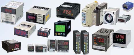 Control Components
 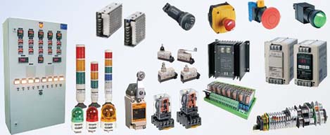 Switching & Accessories
 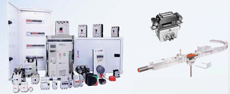 Switchgear and Trolley Systems
 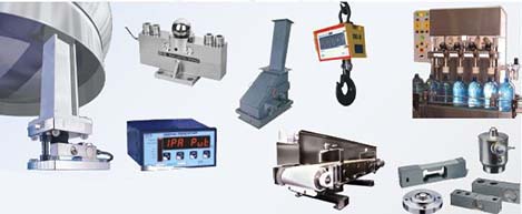 Process Weighing
  LED Lighting
  Omron
Omron
 Mitsubishi
 Delta
Delta
 Autonics
 Inno
Inno
 Panasonic
 Novotechnik
 Orientalmotor
 Microscan
 IPA
IPA
 Technomech
 Intech
 Honeywell
 IOT & Traceability
 Project & Panel Engg.
 Application Case Studies
 Solutions by Industry
 Solutions by Process
 Solutions by Product
 Youtube Videos
 Corporate Information
 Company Profile
 Quality Policy
 Mission Statement
 Chairman's Message
 Intech Group Companies
