 Automation Systems
 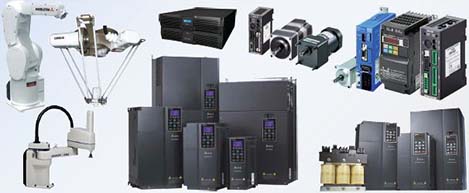 Motion & Power Solutions
  Safety, Vision and IDENT
  Sensing Solutions
  Control Components
  Switching & Accessories
  Switchgear and Trolley Systems
 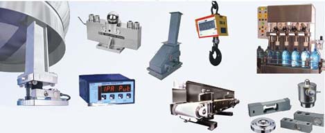 Process Weighing
  LED Lighting
  Omron
Omron
 Mitsubishi
 Delta
Delta
 Autonics
 Inno
Inno
 Panasonic
 Novotechnik
 Orientalmotor
 Microscan
 IPA
IPA
 Technomech
 Intech
 Honeywell
 IOT & Traceability
 Project & Panel Engg.
 Application Case Studies
 Solutions by Industry
 Solutions by Process
 Solutions by Product
 Youtube Videos
 Corporate Information
 Company Profile
 Quality Policy
 Mission Statement
 Chairman's Message
 Intech Group Companies

![E3Z-[]-IL[] Features 5](upload/Images/omron/3542_fe_121-263951.jpg)
![E3Z-[]-IL[] Features 6](upload/Images/omron/3542_fe_221-263952.jpg)
![E3Z-[]-IL[] Features 9](upload/Images/omron/3542_fe_521-263943.jpg)
![E3Z-[]-IL[] Features 12](upload/Images/omron/3542_fe_821-263946.jpg)
![E3Z-[]-IL[] Features 15](upload/Images/omron/3542_fe_1121-263949.jpg)
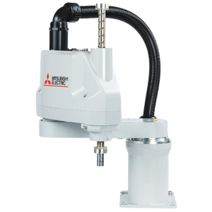
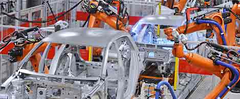
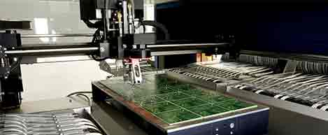
Compact Industrial SCARA
Compact Industrial Robot with light weight space saving arm. Its high speed operation is best suited for pick and place, labelling, tracking

Downtime can be reduced.
Notifies you of faulty parts and such phenomena in the Sensor in real time.
The frequency of sudden failure can be decreased.
The light incident level monitor prevents false detection before it happens.
The efficiency of changeover can be improved.
The batch check for individual sensor IDs significantly decreases commissioning time.
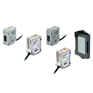
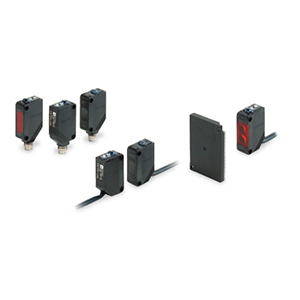
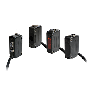
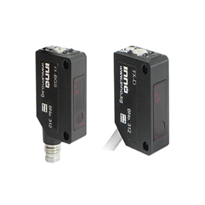
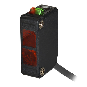
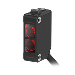
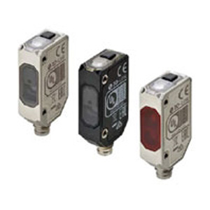
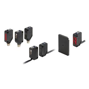
Three types of sensing methods and three types of connection methods are available.
Omron provides two types of Masters, a Master Unit with screw-less clamp terminal blocks and a Master Unit for M12 Smartclick connectors, as IO-Link compliant devices and Sensors for connecting to the screw-less clamp terminals or to the M12 connector terminals that support each Master.
![E3Z-[]-IL[] Features 7](upload/Images/omron/3542_fe_321-263953.jpg)
∙ An abnormality was displayed on the abnormality display screen, but upon going to look at the equipment, no external error was detected and the cause of the stop was not understood...
∙ Those responsible for maintenance investigated the cause of the abnormality from the activity of the stopped equipment, but because the maintenance person relied on the skill he or she has to identify the abnormality and replace the failed sensor, stoppages from 2 hours to several days occur...
![E3Z-[]-IL[] Features 8](upload/Images/omron/3542_fe_421-263942.jpg)
When an abnormality occurs in a sensor, because you can see where the abnormality occurred and the factors estimated for it, you can go to where the abnormality occurred and recover the equipment in the shortest amount of time. Also with wire disconnection detection, not only output wires, but also power lines can be detected unconditionally.
![E3Z-[]-IL[] Features 10](upload/Images/omron/3542_fe_621-263944.jpg)
∙ In a conveyance process operating for 24 hours, dust or dirt accumulated on the detection surface of the photoelectric sensor, leading to a decline in the light incident level that causes the sensor to make false detection and the device to stop...
∙ Water drops stick to the sensing surface of the reflective sensor causing reflected light to enter...
![E3Z-[]-IL[] Features 11](upload/Images/omron/3542_fe_721-263945.jpg)
With a response time of 1 ms, Photoelectric Sensor’s light incident level is output for monitoring. It is output when the light incident level exceeds the instability detection threshold, so you can check the site before false detection occurs and perform predictive maintenance.
![E3Z-[]-IL[] Features 13](upload/Images/omron/3542_fe_921-263947.jpg)
∙ During system start-up or changeover, operators had to perform the I/O check for each of the thousands of sensors installed on the line, and it took an enormous amount of time...
∙ When a sensor is installed wrong or an error occurs, wasteful work occurred that would normally be unnecessary...
![E3Z-[]-IL[] Features 14](upload/Images/omron/3542_fe_1021-263948.jpg)
By checking the sensor identification (manufacturer/sensor type/model number), you can easily check mistakes such as misconnected or unconnected sensors and installation mistakes. Also, because it is possible to program multiple sensors at once using the command language used only for the controller, it is also possible to reduce commissioning time sharply.
Program all at once to reduce commissioning time and inconsistent settings
![E3Z-[]-IL[] Features 16](upload/Images/omron/3542_fe_1221-263950.jpg)
Makes it possible to check for sensor installation mistakes before commissioning
![E3Z-[]-IL[] Features 17](upload/Images/omron/3542_fe_1321-263954.jpg)
E3Z-T81-IL[]
![E3Z-[]-IL[] Dimensions 3](upload/Images/omron/3542_dm_121-262165.gif)
E3Z-T86-IL[]
![E3Z-[]-IL[] Dimensions 4](upload/Images/omron/3542_dm_221-262166.gif)
* Models numbers for Through-beam Sensors (E3Z-T[][]) are for sets that include both the Emitter and Receiver.
The model number of the Emitter is expressed by adding "-L" to the set model number (example: E3Z-T81-IL[]-L 2M),
the model number of the Receiver, by adding "-D" (example: E3Z-T81-IL[]-D 2M.) Refer to Ordering Information to
confirm model numbers for Emitter and Receivers.
E3Z-R81-IL[]
E3Z-D82-IL[]
E3Z-L81-IL[]
![E3Z-[]-IL[] Dimensions 7](upload/Images/omron/3542_dm_321-262167.gif)
E3Z-R86-IL[]
E3Z-D87-IL[]
E3Z-L86-IL[]
![E3Z-[]-IL[] Dimensions 8](upload/Images/omron/3542_dm_421-262168.gif)
Note: The lens for the E3Z-D[]2/D[]7 is black.
E39-S65A
E39-S65B
E39-S65C
![E3Z-[]-IL[] Dimensions 12](upload/Images/omron/3542_dm_521-262169.gif)
E39-S65D
E39-S65E
E39-S65F
![E3Z-[]-IL[] Dimensions 13](upload/Images/omron/3542_dm_621-262170.gif)
E39-L44
![E3Z-[]-IL[] Dimensions 15](upload/Images/omron/3542_dm_721-262171.gif)
E39-L104
![E3Z-[]-IL[] Dimensions 16](upload/Images/omron/3542_dm_821-262172.gif)
Refer to E39-R on your OMRON website for details.
Refer to XS3 or XS5 on your OMRON website for details.