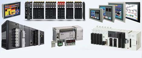
 Automation Systems
 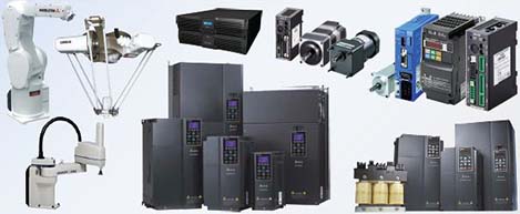 Motion & Power Solutions
 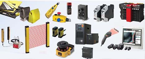 Safety, Vision and IDENT
 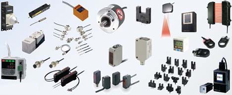 Sensing Solutions
 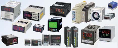 Control Components
 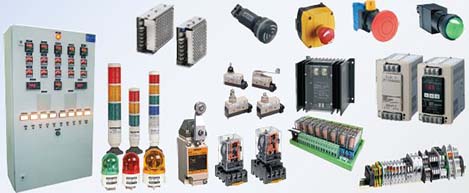 Switching & Accessories
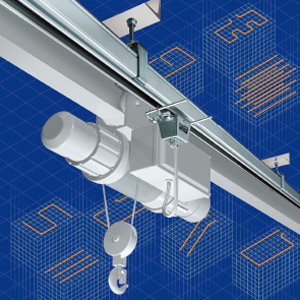
 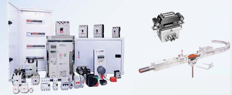 Switchgear and Trolley Systems
 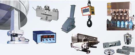 Process Weighing
  LED Lighting
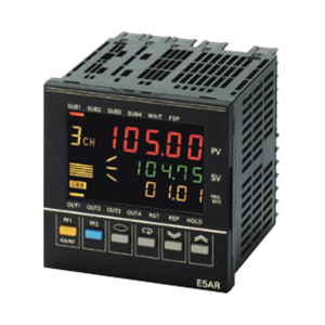
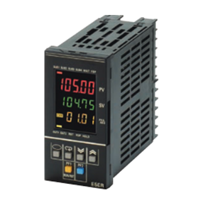
  Omron
Omron
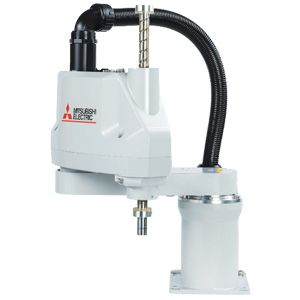
 Mitsubishi
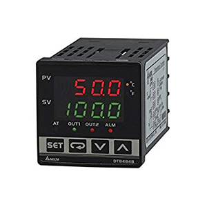
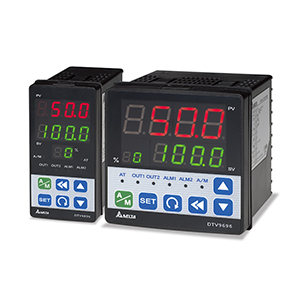
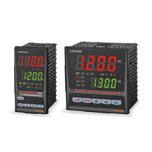
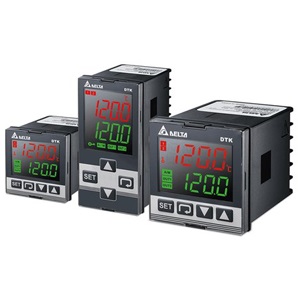
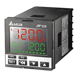
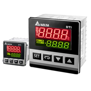
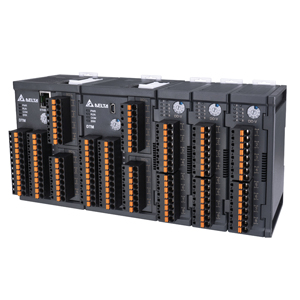
 Delta
Delta
 Autonics
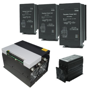
 Inno
Inno
 Panasonic
 Novotechnik
 Orientalmotor
 Microscan
 IPA
IPA
 Technomech
 Intech
 Honeywell
 IOT & Traceability
 Project & Panel Engg.
 Application Case Studies
 Solutions by Industry
 Solutions by Process
 Solutions by Product
 Youtube Videos
 Corporate Information
 Company Profile
 Quality Policy
 Mission Statement
 Chairman's Message
 Intech Group Companies

Compact Industrial SCARA
Compact Industrial Robot with light weight space saving arm. Its high speed operation is best suited for pick and place, labelling, tracking
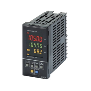

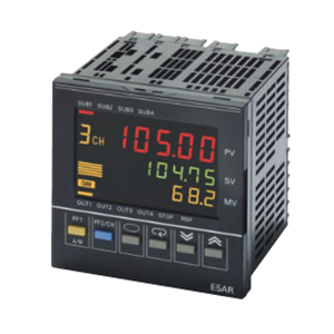
A short sampling period of 50 ms enables use in applications requiring high-speed response.
PV, SP, and MV data is displayed simultaneously in a 3-row, negative LCD display with a backlight.
Multipoint control, cascade control, and proportional control are possible with a single Controller.
When using models with CompoWay/F communications, initial settings can be downloaded and settings can be masked using Support Software (CX-Thermo version 4.0 or higher).
Equipped with calculation functions as a standard (e.g., square root calculation and broken-line approximation).
DeviceNet Communications:
Data setting and monitoring can be performed without any special programming.
|
Supply voltage (See note 1.) |
100 to 240 VAC, 50/60 Hz | 24 VAC, 50/60 Hz; 24 VDC | |
|---|---|---|---|
| Operating voltage range | 85% to 110% of rated supply voltage | ||
| Power consumption | 17 VA max. (with maximum load) | 11 VA/7 W max. (with maximum load) | |
| Sensor input (See note 2.) |
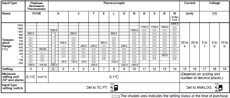
Thermocouple: K, J, T, E, L, U, N, R, S, B, W Platinum resistance thermometer: Pt100 Current input: 4 to 20 mA DC, 0 to 20 mA DC (including remote SP input) Voltage input: 1 to 5 VDC, 0 to 5 VDC, 0 to 10 VDC (including remote SP input) (Input impedance: 150 Ω for current input, approx. 1 MΩ for voltage input) |
||
|
Control output |
Voltage (pulse) output |
12 VDC, 40 mA max. with short-circuit protection circuit | |
| Current output |
0 to 20 mA DC, 4 to 20 mA DC; load: 500 Ω max. (including transfer output) (Resolution: Approx. 54,000 for 0 to 20 mA DC; Approx. 43,000 for 4 to 20 mA DC) |
||
| Relay output |
Position-proportional control type (open, closed) N.O., 250 VAC, 1 A (including inrush current) |
||
| Auxiliary output |
Relay Output N.O., 250 VAC, 1 A (resistive load) Transistor Output Maximum load voltage: 30 VDC; Maximum load current: 50 mA; Residual voltage: 1.5 V max.; Leakage current: 0.4 mA max. |
||
| Potentiometer input | 100 Ω to 2.5 kΩ | ||
|
Event input |
Contact | Input ON: 1 kΩ max.; OFF: 100 kΩ min. | |
| No-contact | Input ON: Residual voltage of 1.5 V max.; OFF: Leakage current of 0.1 mA max. | ||
| Short circuit current: Approx. 4 mA | |||
| Remote SP input | Refer to the information on sensor input. | ||
| Transfer output | Refer to the information on control output. | ||
| Control method | 2-PID or ON/OFF control | ||
| Setting method | Digital setting using front panel keys or setting using serial communications | ||
| Indication method |
7-segment digital display and single-lighting indicator Character Height PV: 9.5 mm; SV: 7.2 mm; MV: 7.2 mm |
||
| Other functions | Depends on model. | ||
|
Ambient operating temperature |
-10 to 55°C (with no icing or condensation) For 3 years of assured use: -10 to 50°C (with no icing or condensation) |
||
|
Ambient operating humidity |
25% to 85% | ||
| Storage temperature | -25 to 65°C (with no icing or condensation) | ||
| Indication accuracy |
Thermocouple input with cold junction compensation: (±0.1% of PV or ±1°C, whichever is greater) ±1 digit max. (See note 1.) Thermocouple input without cold junction compensation: (±0.1% FS or ±1°C, whichever is smaller) ±1 digit (See note 2.) Analog input: ±0.1% FS ±1 digit max. Platinum resistance thermometer input: (±0.1% of PV or ±0.5°C, whichever is greater) ±1 digit max. Position-proportional potentiometer input: ±5% FS ±1 digit max. |
|---|---|
| Control mode |
Standard control (heating or cooling control), heating/cooling control, standard control with remote SP (2-input models only), heating/cooling control with remote SP (2-input models only), cascade standard control (2-input models only), cascade heating/cooling control (2-input models only), proportional control (2-input models only), position-proportional control (control-valve control models only) |
| Influence of temperature |
Thermocouple input (R, S, B, W): (±1% of PV or ±10°C, whichever is greater) ±1 digit max. Other thermocouple input: (±1% of PV or ±4°C, whichever is greater) ±1 digit max. ∗K-type thermocouple at -100°C max.: ±10°C max. Platinum resistance thermometer: (±1% of PV or ±2°C, whichever is greater) ±1 digit max. Analog input: (±1%FS) ±1 digit max. |
| Influence of temperature | |
|
Influence of EMS. (at EN61326-1) |
|
| Control period | 0.2 to 99.0 s (in units of 0.1 s) for time-proportioning control output |
| Proportional band (P) | 0.00% to 999.99% FS (in units of 0.01% FS) |
| Integral time (I) | 0.0 to 3,999.9 s (in units of 0.1 s) |
| Derivative time (D) | 0.0 to 3,999.9 s (in units of 0.1 s) |
| Hysteresis | 0.01% to 99.99% FS (in units of 0.01% FS) |
| Manual reset value | 0.0% to 100.0% (in units of 0.1% FS) |
| Alarm setting range | -19,999 to 99,999 EU (See note 3.) (The decimal point position depends on the input type and the decimal point position setting.) |
| Input sampling period | 50 ms |
| Insulation resistance | 20 MΩ min. (at 500 VDC) |
| Dielectric strength | 2,000 VAC, 50/60 Hz for 1 min (between charged terminals of different polarities) |
| Vibration resistance | 10 to 55 Hz, 20 m/s2 for 10 min each in X, Y, and Z directions |
| Shock resistance | 100 m/s2, 3 times each in X, Y, and Z directions |
| Inrush current |
100 to 240-VAC models: 50 A max. 24 VAC/VDC models: 30 A max. |
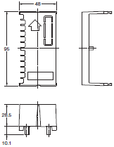
| Weight | Controller only: Approx. 330 g; Mounting bracket: Approx. 60 g; Terminal cover: Approx. 16 g |
| Degree of protection | Front panel: NEMA4X for indoor use (equivalent to IP66); Rear case: IP20; Terminals: IP00 |
| Memory protection | Non-volatile memory (number of writes: 100,000) |
| Applicable standards |
UL61010C-1, CSA C22.2 No. 1010-1 EN61010-1 (IEC61010-1): Pollution degree 2/overvoltage category 2 |
| EMC |
EMI: EN61326-1 (See note 5.) Radiated Interference Electromagnetic Field Strength: EN55011 Group 1 Class A Noise Terminal Voltage: EN55011 Group 1 Class A EMS: EN61326-1 (See note 5.) ESD Immunity: EN61000-4-2: 4 kV contact discharge (level 2) 8 kV air discharge (level 3) Electromagnetic Immunity: EN61000-4-3: 10 V/m (amplitude-modulated, 80 MHz to 1 GHz, 1.4 GHz to 2 GHz) (level 3) Burst Noise Immunity: EN61000-4-4: 2 kV power line (level 3) 2 kV output line (relay output) (level 4) 1 kV measurement line, I/O signal line (level 4) 1 kV communications line (level 3) Conducted Disturbance Immunity: EN61000-4-6: 3 V (0.15 to 80 MHz) (level 3) Surge Immunity: EN61000-4-5: 1 kV line to line (power line, output line (relay output)) (level 2) 2 kV line to ground (power line, output line (relay output)) (level 3) Power Frequency Magnetic Field Immunity: EN61000-4-8: 30 A/m (50 Hz) continuous field Voltage Dip/Interrupting Immunity: EN61000-4-11: 0.5 cycle, 100% (rated voltage) |
| Transmission path connection | Multiple points |
|---|---|
| Communications method | RS-485 (two-wire, half duplex) |
| Synchronization method | Start-stop synchronization |
| Baud rate | 9,600, 19,200, or 384,000 bps |
| Transmission code | ASCII |
| Data bit length | 7 or 8 bits |
| Stop bit length | 1 or 2 bits |
| Error detection |
Vertical parity (none, even, odd) Block check character (BCC): CompoWay/F CRC-16: Modbus |
| Flow control | None |
| Interface | RS-485 |
| Retry function | None |
| Communications buffer | 217 bytes |
| Communications response send wait time | 0 to 99 ms, Default: 20 ms |
| Item | Specifications | ||||
|---|---|---|---|---|---|
| Communications protocol | Conforms to DeviceNet | ||||
|
Communications functions |
Remote I/O communications |
• Master-slave connections (polling, bit-strobe, COS, or cyclic) • Conform to DeviceNet specifications. |
|||
| I/O allocations |
• Can allocate any I/O data from the Configurator. • Can allocate any data, such as parameters specific to the Devicenet, and the Digital Controller variable area. • Up to 2 blocks for the IN Area, up to a total of 100 words. • One block for the OUT Area, up to 100 words (first word is always allocated to Output Enable Bits). |
||||
|
Message communications |
• Explicit message communications • CompoWay/F communications commands can be sent (commands are sent in explicit message format). |
||||
| Connection format | Combination of multidrop and T-branch connections (for trunk and drop lines) | ||||
| Baud rate | DeviceNet: 500, 250, or 125 kbps, or automatic detection of master baud rate | ||||
| Communications media | Special 5-wire cable (2 signal lines, 2 power lines, and 1 shield line) | ||||
| Communications distance | Baud rate | Network length | Drop line length | Total drop line length | |
| 500 kbps | 100 m max. (100 m max.) | 6 m max. | 39 m max. | ||
| 250 kbps | 250 m max. (100 m max.) | 6 m max. | 78 m max. | ||
| 125 kbps | 500 m max. (100 m max.) | 6 m max. | 156 m max. | ||
| The values in parentheses apply when Thin Cables are used. | |||||
| Supply voltage | DeviceNet power supply: 24 VDC | ||||
| Allowable voltage range | DeviceNet power supply: 11 to 25 VDC | ||||
| Current consumption | 50 mA max. (24 VDC) | ||||
|
Maximum number of nodes that can be connected |
64 (includes Configurator when used) | ||||
|
Maximum number of slaves that can be connected |
63 | ||||
| Error control | CRC error detection | ||||
| Power supply | Power supplied from DeviceNet communications connector. | ||||
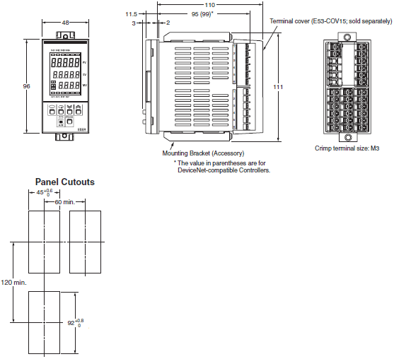

Order the Rubber Packing separately if it becomes lost or damaged. (Refer to Data Sheet.)
The Rubber Packing can be used to achieve an IP66 degree of protection.
(Deterioration, shrinking, or hardening of the rubber packing may occur depending on the operating environment. Therefore, periodic replacement is recommended to ensure the level of waterproofing specified in NEMA4. The time for periodic replacement depends on the operating environment. Be sure to confirm this point at your site. Consider one year a rough standard. OMRON shall not be liable for the level of water resistance if the customer does not perform periodic replacement.)
The Rubber Packing does not need to be attached if a waterproof structure is not required.
One set is packaged with the product.
Order Mounting Adapters separately if yours are lost or damaged.