With Pressure Sensors, changes in pressure can be measured to confirm suction, verify mounting, manage source pressures, and test for leaking. Differential Pressure Flow Sensors are also available.
A pressure sensor is a device equipped with a pressure-sensitive element that measures the pressure of a gas or a liquid against a diaphragm made of stainless steel, silicon, etc., and converts the measured value into an electrical signal as an output.
A semiconductor piezo-resistance dispersion pressure sensor has a semiconductor distortion gauge formed on the surface of the diaphragm, and it converts changes in electrical resistance into an electrical signal by means of the piezo-resistance effect that occurs when the diaphragm is distorted due to an external force (pressure).
A static capacitance pressure sensor has a capacitor that is formed by a static glass electrode and an opposing movable silicon electrode, and it converts changes in static capacitance that occur when the movable electrode is distorted due to an external force (pressure) into an electrical signal. (The E8Y uses the static capacitance method, and other models use the semiconductor method.)

Ultrasound waves move straight forward in a uniform medium, and are reflected and transmitted at the boundary between differing media. This phenomenon is affected by the type and shape of the media. A human body in air causes considerable reflection and can be easily detected.

The electrical resistance of the above conductor is expressed by the following formula: R = ? × L/S.
When this conductor is pulled to the right or left as shown below, the length increases and the cross-sectional area decreases.

The electrical resistance of the above conductor is expressed by the following formula: R' = ? ×(L+1)/S-s.
Accordingly,
R' > R.
This shows how the application of a mechanical force changes the electrical resistance.
The amount of pressure is expressed in terms of atmospheric pressure. It is referred to as "positive pressure" when it is greater than one atmosphere, and "negative pressure" when it is less than one atmosphere.
This is the amount of pressure expressed in relation to an absolute vacuum.
This is the amount of pressure compared to any particular pressure (the reference pressure).

The pressure of the atmosphere. The standard atmospheric pressure (1 atm) is equal to the pressure of a column of mercury with a height of 760 mm.
A pressure less than one atmosphere.
The range of pressure that can be detected by the Sensor.
The pressure that must be withstood without degraded performance after returning to the pressure detection range.
Repeat accuracy refers to the deviation in the operating point when the output inverts while pressure is increased or decreased at a temperature of 23°C, divided by the full scale of the pressure detection range.

This is the deviation from the rated output current (4 mA, 20 mA) when zero pressure and the rated output are applied at a temperature of 23°C, divided by the full-scale value.
It is expressed in units of %F.S.
The analog output changes in an approximately linear fashion with respect to the detected pressure. The change, however, deviates slightly from an ideal straight line. This deviation is expressed as a percentage of the full scale.

An ideal straight line is drawn between the output current (or voltage) at zero pressure and the rated current (or voltage), and the difference between the measured current (or voltage) and the ideal current (voltage) is obtained as an error. The error as the pressure rises and the error as the pressure falls are obtained, and the maximum value of the absolute value of the difference between the rising error and falling error is divided by the full scale current (or voltage). This is the linear hysteresis, and it is expressed in units of %FS.
The difference between the output ON pressure and OFF pressure is divided by the full pressure scale.

Substances contained in the air (nitrogen, carbon dioxide, etc.) and inert gases (argon, neon, etc.).
A new Measurement Law was enacted in Japan on November 1, 1993. This law prohibits the use of Torr for anything except internal human body pressure measurements. From September 30, 1999, the use of kgf/m², mHg (except for blood pressure measurements), and mH2O was prohibited.

Figure 1

Ro : Output impedance
Rx : Load resistance
Eo : Output voltage (terminals open)
Ex : Output voltage (with load Zx connected)
Ix : Load current (with load Zx connected)
In Figure 1, the current (Ix) that flows when the load resistance (Rx) is connected is calculated as follows:

The output impedance (Ro) in Equation (1) is calculated as follows:

The voltage (Eo) is measured when the output is open, followed by the voltage (Ex) when a load resistance (for example, the minimum value of the permitted load resistance of a transducer) is connected.
The measured values Eo and Ex and the connected load resistance (Rx) are inserted into Equation 2 to calculate the output impedance (Ro) of the transducer.
In Figure 2, the voltage (Ex) of the output terminals when the load resistance (Rx) is connected is calculated as follows:

The output impedance in Equation (3) is calculated as follows:

Here, the current (Io) is measured with the output short-circuited.
Figure 2

Ro : Output impedance
Rx : Load resistance
Io : Output current (output terminal short-circuited)
Ix : Output current (with load Rx connected)
Ex : Output voltage (with load Rx connected)
Next, the output current (Ix) is measured when a load resistance (for example, the maximum value of the permitted load resistance of a transducer) is connected. The measured values Io and Ix and the value of the connected load resistance (Rx) are inserted into Equation 4, and the output impedance (Ro) of the transducer is calculated. The output impedance of the transducer introduced here is the value for normal operation.
In general, it is best to make the output impedance of a voltage output transducer as small as possible, i.e., as close to 0 W as possible, to minimize the effects of load fluctuations on the transducer. For a current output transducer, the opposite is true: the higher the impedance (the closer to infinite impedance), the better.

 Automation Systems
 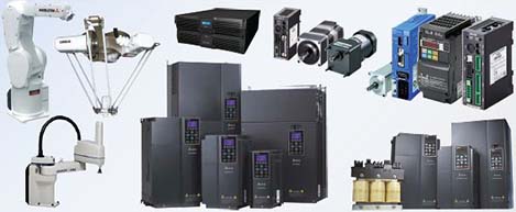 Motion & Power Solutions
 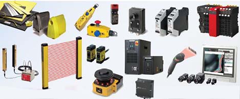 Safety, Vision and IDENT
 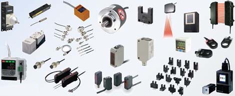 Sensing Solutions
 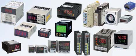 Control Components
 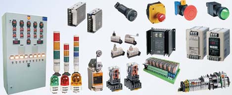 Switching & Accessories
 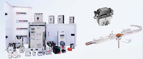 Switchgear and Trolley Systems
 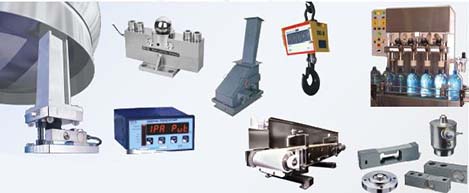 Process Weighing
  LED Lighting
  Omron
Omron
 Mitsubishi
 Delta
Delta
 Autonics
 Inno
Inno
 Panasonic
 Novotechnik
 Orientalmotor
 Microscan
 IPA
IPA
 Technomech
 Intech
 Honeywell
 IOT & Traceability
 Project & Panel Engg.
 Application Case Studies
 Solutions by Industry
 Solutions by Process
 Solutions by Product
 Youtube Videos
 Corporate Information
 Company Profile
 Quality Policy
 Mission Statement
 Chairman's Message
 Intech Group Companies
