Proximity Sensors are available in models using high-frequency oscillation to detect ferrous and non-ferrous metal objects and in capacitive models to detect non-metal objects. Models are available with environment resistance, heat resistance, resistance to chemicals, and resistance to water.
"Proximity Sensor" includes all sensors that perform non-contact detection in comparison to sensors, such as limit switches, that detect objects by physically contacting them. Proximity Sensors convert information on the movement or presence of an object into an electrical signal. There are three types of detection systems that do this conversion: systems that use the eddy currents that are generated in metallic sensing objects by electromagnetic induction, systems that detect changes in electrical capacity when approaching the sensing object, and systems that use magnets and reed switches.
The Japanese Industrial Standards (JIS) define proximity sensors in JIS C 8201-5-2 (Low-voltage switch gear and control gear, Part 5: Control circuit devices and switching elements, Section 2: Proximity sensors), which conforms to the IEC 60947-5-2 definition of non-contact position detection switches.
JIS gives the generic name "proximity sensor" to all sensors that provide non-contact detection of target objects that are close by or within the general vicinity of the sensor, and classifies them as inductive, capacitive, ultrasonic, photoelectric, magnetic, etc.
This Technical Guide defines all inductive sensors that are used for detecting metallic objects, capacitive sensors that are used for detecting metallic or non-metallic objects, and sensors that utilize magnetic DC fields as Proximity Sensors.
Devices such as limit switches detect an object by contacting it, but Proximity Sensors are able to detect the presence of the object electrically, without having to touch it.
Proximity Sensors use semiconductor outputs, so there are no contacts to affect the service life.
Detection takes place with almost no effect from dirt, oil, or water on the object being detected. Models with fluororesin cases are also available for excellent chemical resistance.
For information on high-speed response, refer to Explanation of Terms.
Proximity Sensors can be used in temperatures ranging from -40 to 200°C.
Proximity Sensors detect the physical changes of an object, so they are almost completely unaffected by the object's surface color.
Both Inductive and Capacitive Proximity Sensors are affected by interaction with other Sensors. Because of this, care must be taken when installing them to prevent mutual interference. Care must also be taken to prevent the effects of surrounding metallic objects on Inductive Proximity Sensors, and to prevent the effects of all surrounding objects on Capacitive Proximity Sensors.
Inductive Proximity Sensors detect magnetic loss due to eddy currents that are generated on a conductive surface by an external magnetic field. An AC magnetic field is generated on the detection coil, and changes in the impedance due to eddy currents generated on a metallic object are detected.
Other methods include Aluminum-detecting Sensors, which detect the phase component of the frequency, and All-metal Sensors, which use a working coil to detect only the changed component of the impedance. There are also Pulse-response Sensors, which generate an eddy current in pulses and detect the time change in the eddy current with the voltage induced in the coil.
The sensing object and Sensor form what appears to be a transformer-like relationship.

The transformer-like coupling condition is replaced by impedance changes due to eddy-current losses.
The impedance changes can be viewed as changes in the resistance that is inserted in series with the sensing object. (This does not actually occur, but thinking of it this way makes it easier to understand qualitatively.)

Capacitive Proximity Sensors detect changes in the capacitance between the sensing object and the Sensor. The amount of capacitance varies depending on the size and distance of the sensing object. An ordinary Capacitive Proximity Sensor is similar to a capacitor with two parallel plates, where the capacity of the two plates is detected. One of the plates is the object being measured (with an imaginary ground), and the other is the Sensor's sensing surface. The changes in the capacity generated between these two poles are detected.
The objects that can be detected depend on their dielectric constant, but they include resin and water in addition to metals.

The reed end of the switch is operated by a magnet. When the reed switch is turned ON, the Sensor is turned ON.


A sensing object that serves as a reference for measuring basic performance, and that is made of specified materials and has a specified shape and dimensions.

The distance from the reference position (reference surface) to the measured operation (reset) when the standard sensing object is moved by the specified method.

The distance from the reference surface that allows stable use, including the effects of temperature and voltage, to the (standard) sensing object transit position. This is approximately 70% to 80% of the normal (rated) sensing distance.

With respect to the distance between the standard sensing object and the Sensor, the difference between the distance at which the Sensor operates and the distance at which the Sensor resets.

t1: The interval from the point when the standard sensing object moves into the sensing area and the Sensor activates, to the point when the output turns ON.
t2: The interval from the point when the standard sensing object moves out of the Sensor sensing area to the point when the Sensor output turns OFF.

The number of detection repetitions that can be output per second when the standard sensing object is repeatedly brought into proximity.
See the accompanying diagram for the measuring method.

With a Shielded Sensor, magnetic flux is concentrated in front of the Sensor and the sides of the Sensor coil are covered with metal.
The Sensor can be mounted by embedding it into metal.

With an Unshielded Sensor, magnetic flux is spread widely in front of the Sensor and the sides of the Sensor coil are not covered with metal.
This model is easily affected by surrounding metal objects (magnetic objects), so care must be taken in selecting the mounting location.


Take the following points into account when selecting a DC 2-wire model (polarity/no-polarity).

 Automation Systems
 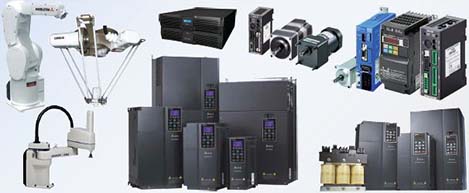 Motion & Power Solutions
 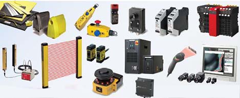 Safety, Vision and IDENT
 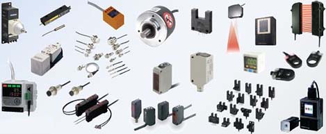 Sensing Solutions
 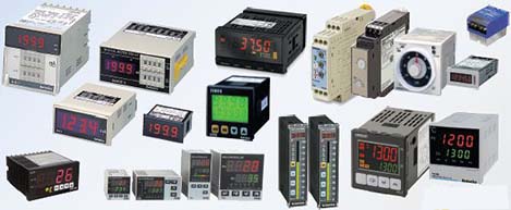 Control Components
 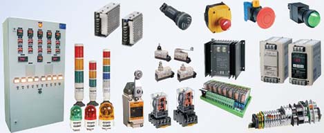 Switching & Accessories
 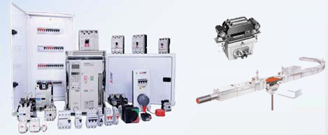 Switchgear and Trolley Systems
 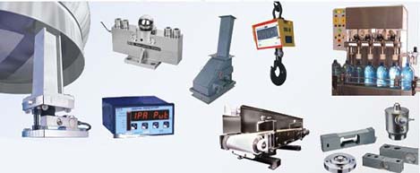 Process Weighing
  LED Lighting
  Omron
Omron
 Mitsubishi
 Delta
Delta
 Autonics
 Inno
Inno
 Panasonic
 Novotechnik
 Orientalmotor
 Microscan
 IPA
IPA
 Technomech
 Intech
 Honeywell
 IOT & Traceability
 Project & Panel Engg.
 Application Case Studies
 Solutions by Industry
 Solutions by Process
 Solutions by Product
 Youtube Videos
 Corporate Information
 Company Profile
 Quality Policy
 Mission Statement
 Chairman's Message
 Intech Group Companies
