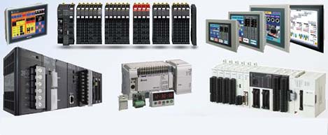
 Automation Systems
 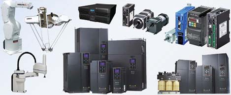 Motion & Power Solutions
 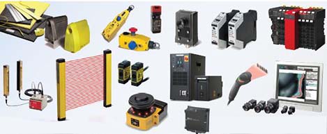 Safety, Vision and IDENT
 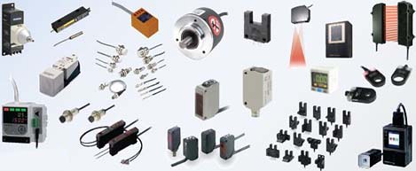 Sensing Solutions
 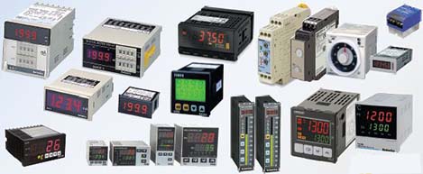 Control Components
 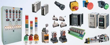 Switching & Accessories
 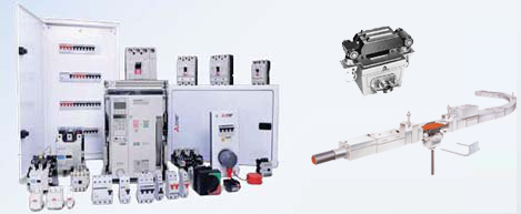 Switchgear and Trolley Systems
 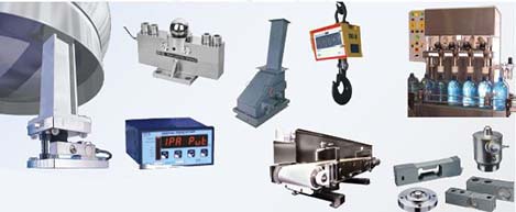 Process Weighing
  LED Lighting
  Omron
Omron
 Mitsubishi
 Delta
Delta
 Autonics
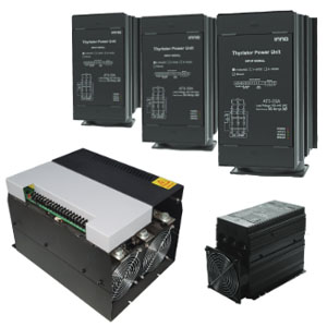
 Inno
Inno
 Panasonic
 Novotechnik
 Orientalmotor
 Microscan
 IPA
IPA
 Technomech
 Intech
 Honeywell
 IOT & Traceability
 Project & Panel Engg.
 Application Case Studies
 Solutions by Industry
 Solutions by Process
 Solutions by Product
 Youtube Videos
 Corporate Information
 Company Profile
 Quality Policy
 Mission Statement
 Chairman's Message
 Intech Group Companies

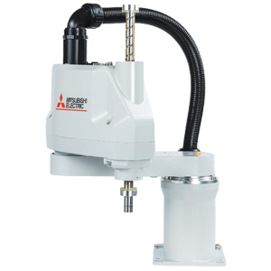
Compact Industrial SCARA
Compact Industrial Robot with light weight space saving arm. Its high speed operation is best suited for pick and place, labelling, tracking
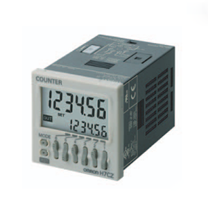

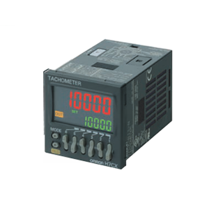
Character height of 10 mm with a wide viewing angle.

Operation is simplified by the Up Key for each digit.

Power supply circuit and input circuits are isolated inside the counter.
Previous non-isolated counters had wiring restrictions and could be damaged if wired incorrectly. The H7CZ removes these worries.
You can set an upper limit for the set value to prevent unexpected operation of output devices caused by setting mistakes.

The output counter counts the number of times the output turns on (alarms can be displayed and the count can be monitored in increments of 1,000 operations). this counter is useful in managing the service life of the counter or the load.
Worry-free application is possible in locations subject to water.
Note: When the Y92S-29 waterproof packing is used.
Select from any of seven protection patterns. Use the best one for the application.
last update: August 03, 2015
| Models | H7CZ-L8 | H7CZ-L8D1 | |
|---|---|---|---|
| Configuration | 1-stage preset counter | ||
| Ratings | Power supply voltage *1 | 100 to 240 VAC, 50/60 Hz | 24 VAC, 50/60 Hz or 12 to 24 VDC |
|
Operating voltage fluctuation range |
85% to 110% of rated supply voltage (12 to 24 VDC: 90% to 110%) | ||
| Power consumption |
Approx. 9.4 VA at 100 to 240 VAC, Approx. 7.2 VA/4.7 W at 24 VAC/12 to 24 VDC |
||
| Mounting method | Flush mounting or surface mounting | ||
| External connections | 8-pin socket | ||
| Degree of protection |
IEC IP66, UL508 Type 4X (indoors) for panel surface only and only when Y92S- 29 Waterproof Packing is used. |
||
| Input signals | Count, Reset | ||
| Counter | Maximum counting speed | 30 Hz or 10 kHz (switchable) (ON/OFF ratio 1:1) | |
| Input mode | Increment, Decrement | ||
| Output mode | N, F, C, R, K-1, P, Q, and A. | ||
| One-shot output time | 0.01 to 99.99 s | ||
| Reset system |
External (minimum reset signal width: 1 ms or 20 ms, selectable), Manual, and Automatic reset (internal according to C, R, P, and Q mode operation) |
||
| Prescaling function | Yes (0.001 to 99.999) | ||
| Decimal point adjustment | Yes (rightmost 3 digits) | ||
| Sensor waiting time |
290 ms max. (Control output is turned OFF and no input is accepted during sensor waiting time.) |
||
| Input method |
No-voltage inputs: ON impedance: 1 kΩ max. (Leakage current: 12 mA at 0 Ω) ON residual voltage: 3 V max. OFF impedance: 100 kΩ min. |
||
| Control output |
3 A at 250 VAC/30 VDC, resistive load (cosφ=1), Minimum applied load: 10 mA at 5 VDC (failure level: P, reference value) |
||
| Display *2 |
LCD Character height Count value: 10 mm Set value: 6 mm |
||
| Digits |
6 digits -99999 to 999999 (-5 digits to +6 digits) |
||
| Memory backup | EEPROM (overwrites: 100,000 times min.) that can store data for 10 years min. | ||
| Operating temperature range |
-10 to 55°C (-10 to 50°C if Counters are mounted side by side) (with no icing or condensation) |
||
| Storage temperature range | -25 to 70°C (with no icing or condensation) | ||
| Operating humidity range | 25% to 85% | ||
| Front panel color | Light gray (5Y7/1) | ||
*1. Do not use the output from an inverter as the power supply.The ripple must be 20% maximum for DC power.
*2. The display is lit only when the power is ON. Nothing is displayed when power is OFF.
| Insulation resistance |
100 MΩ min. (at 500 VDC) between current-carrying terminals and exposed non- current-carrying metal parts, and between non-continuous contacts |
|
|---|---|---|
| Dielectric strength |
2,000 VAC, 50/60 Hz for 1 min between current-carrying metal parts and non-current- carrying metal parts 2,000 VAC, 50/60 Hz for 1 min between power supply and input circuit (1,000 VAC for 24 VAC/12 to 24 VDC) 1,000 VAC, 50/60 Hz for 1 min between control output, power supply, and input circuit (2,000 VAC) 1,000 VAC, 50/60 Hz for 1 min between non-continuous contacts |
|
| Impulse withstand voltage |
3.0 kV between power terminals (1.0 kV for models with 24 VAC/12 to 24 VDC) 4.5 kV between current-carrying terminals and exposed non-current-carrying metal parts (1.5 kV for models with 24 VAC/12 to 24 VDC) |
|
| Noise immunity |
±1.5 kV between power terminals ±600 V between input terminals Square-wave noise by noise simulator (pulse width: 100 ns/1 μs, 1-ns rise) |
|
| Static immunity |
Malfunction: 8 kV Destruction: 15 kV |
|
|
Vibration resistance |
Destruction | 10 to 55 Hz with 0.75-mm single amplitude each in three directions for 2 h each |
| Malfunction | 10 to 55 Hz with 0.35-mm single amplitude each in three directions for 10 min each | |
|
Shock resistance |
Destruction | 300 m/s2 each in three directions |
| Malfunction | 100 m/s2 each in three directions | |
| Life expectancy |
Mechanical: 10,000,000 operations min. Electrical: 100,000 operations min. (3 A at 250 VAC, resistive load, ambient temperature condition: 23°C)* |
|
| Weight | Approx. 100 g (Counter only) | |
* Refer to the Life-test Curve.


A current of 0.15 A max. can be switched at 125 VDC (cosφ=1) and current of 0.1 A max. can be switched if L/R=7 ms. In both cases, a life of 100,000 operations can be expected.
|
Approved safety standards |
cULus (or cURus): UL508/CSA C22.2 No. 14 *1 EN 61010-1 (IEC 61010-1): Pollution degree 2/overvoltage category II B300 PILOT DUTY 1/4 HP 120 VAC, 1/3 HP, 240 VAC, 3 A resistive load VDE0106/P100 (finger protection) |
|---|---|
| EMC |
(EMI) EN61326-1 *2 Emission Enclosure: EN 55011 Group 1 class A Emission AC mains: EN 55011 Group 1 class A (EMS) EN61326-1 *2 Immunity ESD: EN 61000-4-2: 4 kV contact discharge; 8 kV air discharge Immunity RF-interference: EN 61000-4-3: 10 V/m (Amplitude-modulated, 80 MHz to 1 GHz); 10 V/m (Pulse-modulated, 900 MHz ±5 MHz) Immunity Conducted Disturbance: EN 61000-4-6: 10 V (0.15 to 80 MHz) Immunity Burst: EN 61000-4-4: 2 kV power-line; 1 kV I/O signal-line Immunity Surge: EN 61000-4-5: 1 kV line to lines (power and output lines); 2 kV line to ground (power and output lines) Immunity Voltage Dip/Interruption: EN 61000-4-11: 0.5 cycle, 100% (rated voltage) |
*1. The following safety standards apply to H7CZ.
cUL (Listing): Applicable when an OMRON P2CF(-E) Socket is used.
cUR (Recognition): Applicable when any other socket is used.
*2. Industrial electromagnetic environment (EN/IEC 61326-1 Table 2)
| Inputs | Count |
• Reads counting signals. • Increment and decrement inputs accepted. |
|---|---|---|
| Reset |
• Resets present value and outputs.*2 • Counting cannot be performed during reset input. • Reset indicator is lit while reset input is ON. |
|
| Outputs | OUT | Outputs signals according to the specified output mode when a set value is reached. |
*1. For information on operation of I/O functions, refer to Catalog.
*2. In elapsed time mode, the present value returns to 0; in remaining time mode, the present value returns to the set
value.
The following table shows the delay from when the reset signal is input until the output is turned OFF. (Reference values)
| Minimum reset signal width | Output delay time |
|---|---|
| 1 ms | 0.8 to 1.2 ms |
| 20 ms | 15 to 25 ms |
last update: August 03, 2015
last update: December 19, 2013


Panel cutouts are as shown below. (according to DIN43700).

Note: 1. The mounting panel thickness should be 1 to 5 mm.
2. To allow easier operation, it is recommended that Adapters be mounted so that the gap between sides with
hooks is at least 15 mm (i.e., with the panel cutouts separated by at least 60 mm).
3. It is possible to horizontally mount Timers side by side. Attach the Flush Mounting Adapters so that the surfaces
without hooks are on the sides of the Timers. If they are mounted side-by-side, water-resistance will be lost.


* These dimensions depend on the kind of DIN Track. (Reference value)