 Automation Systems
 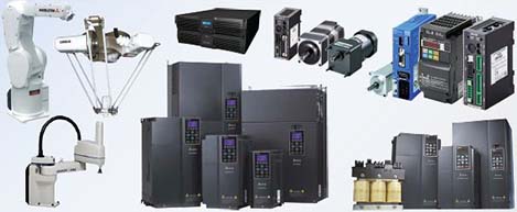 Motion & Power Solutions
  Safety, Vision and IDENT
 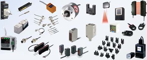 Sensing Solutions
  Control Components
 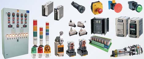 Switching & Accessories
 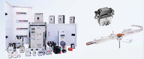 Switchgear and Trolley Systems
 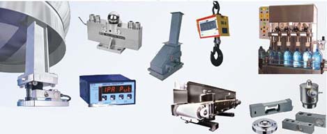 Process Weighing
  LED Lighting
  Omron
Omron
 Mitsubishi
 Delta
Delta
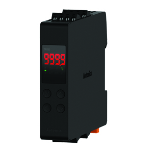
 Autonics
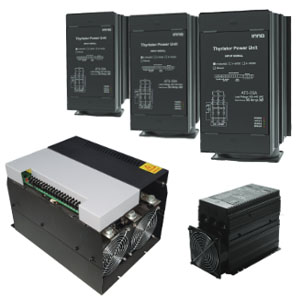
 Inno
Inno
 Panasonic
 Novotechnik
 Orientalmotor
 Microscan
 IPA
IPA
 Technomech
 Intech
 Honeywell
 IOT & Traceability
 Project & Panel Engg.
 Application Case Studies
 Solutions by Industry
 Solutions by Process
 Solutions by Product
 Youtube Videos
 Corporate Information
 Company Profile
 Quality Policy
 Mission Statement
 Chairman's Message
 Intech Group Companies

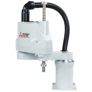
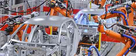
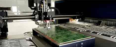
Compact Industrial SCARA
Compact Industrial Robot with light weight space saving arm. Its high speed operation is best suited for pick and place, labelling, tracking
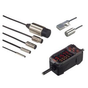

Small Sensor Heads are perfect for detecting the height of small objects and for applications where multiple Sensor Heads are used.

Sensors with stainless steel Protective Spiral Tubes are also available.

The temperature characteristic ranks at the top in the industry at 0.1% FS/°C for heat-resistive sensors, and it ranges up to 200°C for flat sensors.

The Amplifier Unit can be used as is when replacing damaged Sensor Heads or changing the Sensor Head for different detection distances.

The distance between the Amplifier Units the Sensor Heads can be extended to 3 m, 6 m, or 10 m using a ZX-XC[]A Cable (sold separately).

Adjustments using the adjustment knob are no longer required to adjust linearity. Linearity adjustment is completed simply by teaching at 0%, 50%, and 100% of the measurement distance, greatly reducing setting time.

Linearity is worse for non-ferrous than ferrous sensing objects. A material selection function has been developed to improve linearity with stainless steel and aluminum sensing objects.

Multiple Sensors may be used in confined spaces for level difference measurements or multiple-point measurements. Mutual interference between up to 5 Sensors can be prevented simply by connecting Calculating Units to eliminate the need for timing signals on the user side.

The calculation results from two Sensors can be displayed on the Amplifier for one Sensor simply by placing a Calculating Unit between the Amplifier Units. The required parameters need to be input only into one Amplifier Unit.