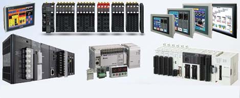
 Automation Systems
 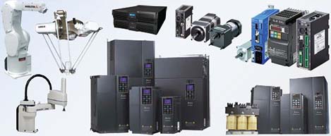 Motion & Power Solutions
 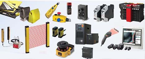 Safety, Vision and IDENT
 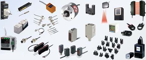 Sensing Solutions
 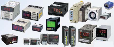 Control Components
 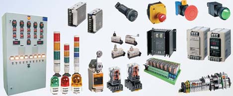 Switching & Accessories
 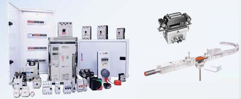 Switchgear and Trolley Systems
 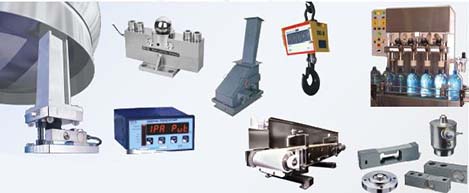 Process Weighing
  LED Lighting
  Omron
Omron
 Mitsubishi
 Delta
Delta
 Autonics
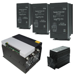
 Inno
Inno
 Panasonic
 Novotechnik
 Orientalmotor
 Microscan
 IPA
IPA
 Technomech
 Intech
 Honeywell
 IOT & Traceability
 Project & Panel Engg.
 Application Case Studies
 Solutions by Industry
 Solutions by Process
 Solutions by Product
 Youtube Videos
 Corporate Information
 Company Profile
 Quality Policy
 Mission Statement
 Chairman's Message
 Intech Group Companies

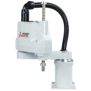
Compact Industrial SCARA
Compact Industrial Robot with light weight space saving arm. Its high speed operation is best suited for pick and place, labelling, tracking

last update: July 13, 2016
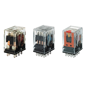
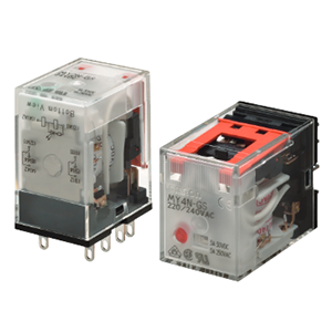
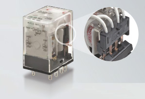
OMRON insists on inhouse production from component molds to manufacturing facilities to better meet your needs.
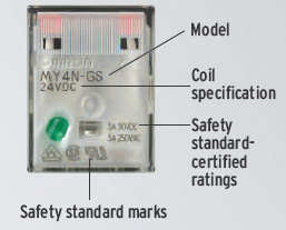
The model, specifications, and safety standards are all provided on the top surface.
You can check this information while the Relay is mounted in the Socket.
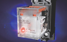
Mechanical indicators are now a standard feature so that you know the contact operating status even for standard models.
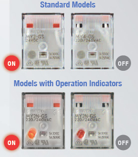
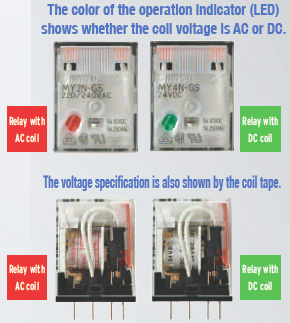
To prevent incorrectly using the Relays, we’ve made it easy to tell the difference between Relays with different specifications.
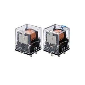
High Electrical Durability
Helps reduce the maintenance frequency.
Two-pole Relay: 500,000 operations
Four-pole Relay: 200,000 operations
Note. For switching the rated load. Refer to the datasheet for details.
Wide Ambient Operating Temperature
Reliable application is possible for high-density mounting and in cold locations.
Ambient operating temperature: -55 to 70°C

High Shock Resistance
Reduces malfunctions for unexpected external shocks.
Malfunction shock resistance: 20G
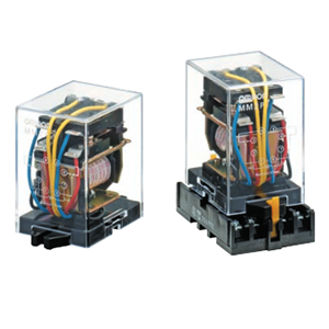
We took 50 years of manufacturing experience and designed market needs into design and production.
Examples: Connection reliability was achieved with welding and one-piece molding while stable quality was achieved in automatic manufacturing.
| Item |
Rated current (mA) |
Coil resis- tance (Ω) |
Coil inductance (H) |
Must- operate voltage |
Must- release voltage |
Maxi- mum voltage |
Power consumption (VA, W) |
|||
|---|---|---|---|---|---|---|---|---|---|---|
| Rated voltage | 50 Hz | 60 Hz |
Armature OFF |
Armature ON |
Percentage of rated voltage | |||||
| AC | 12 | 106.5 | 91 | 46 | 0.17 | 0.33 | 80% max. *1 | 30% min. *2 | 110% |
Approx. 0.9 to 1.3 (at 60 Hz) |
| 24 | 53.8 | 46 | 180 | 0.69 | 1.3 | |||||
| 48 | 25.7 | 21.1 | 788 | 3.22 | 5.66 | |||||
| 100/110 | 11.7/12.9 | 10.0/11.0 | 3,750 | 14.54 | 24.6 | |||||
| 110/120 | 9.9/10.8 | 8.4/9.2 | 4,430 | 19.2 | 32.1 | |||||
| 200/220 | 6.2/6.8 | 5.3/5.8 | 12,950 | 54.75 | 94.07 | |||||
| 220/240 | 5.2/6.2 | 4.3/5.0 | 15,920 | 83.5 | 136.4 | |||||
| DC | 6 | 146 (151) |
41.0 (39.8) |
0.17 | 0.33 | 10% min. *2 | Approx. 0.9 | |||
| 12 | 72.7 (75) |
165 (160) |
0.73 | 1.37 | ||||||
| 24 | 36.3 (37.7) |
662 (636) |
3.2 | 5.72 | ||||||
| 48 | 17.6 (18.8) |
2,725 (2,560) |
10.6 | 21.0 | ||||||
| 100/110 | 8.7 (9.0)/9.6 (9.9) |
11,440 (11,100) |
45.6 | 86.2 | ||||||
| 220 | 3.6 | 60394 | 362.3 | 452.9 | Approx. 0.8 | |||||
Note:
1. The rated current and coil resistance are measured at a coil temperature of 23°C with tolerances of +15%/−20% for the AC rated current and +15% for the DC coil resistance.
2. The AC coil resistance and inductance values are reference values only (at 60 Hz).
3. Operating characteristics were measured at a coil temperature of 23°C.
4. The values in parentheses for the rated currents and coil voltages of DC coils are for models with LED operation indicators.
5. The maximum voltage capacity was measured at an ambient temperature of 23°C.
*1. There is variation between products, but actual values are 80% max.
The Relay will operate if 80% or higher of the rated voltage is applied. However, to achieve the specified characteristics, apply the rated voltage to the coil.
*2. There is variation between products, but actual values are 30% minimum for AC and 10% minimum for DC. To ensure release, use a value that is lower than the specified value.
| 2 poles | 4 poles | |||
|---|---|---|---|---|
| Resistive load |
Inductive load (cos φ = 0.4, L/R = 7 ms) |
Resistive load |
Inductive load (cos φ = 0.4, L/R = 7 ms) |
|
| Contact configuration | DPDT | 4PDT | ||
| Contact structure | Single | |||
| Contact material | Ag | |||
| Rated load |
5 A at 220 VAC 5 A at 24 VDC |
2 A at 220 VAC 2 A at 24 VDC |
3 A at 220 VAC 3 A at 24 VDC |
0.8 A at 220 VAC 1.5 A at 24 VDC |
| Rated carry current | 5 A | 3 A | ||
| Maximum contact voltage | 250 VAC, 220 VDC | 250 VAC, 220 VDC | ||
| Maximum contact current | 5 A | 3 A | ||
| Maximum switching capacity |
1,100 VA 120 W |
440 VA 48 W |
660 VA 72 W |
176 VA 36 W |
|
Minimum load (reference values)* |
1 mA at 5 VDC | |||
* These values are guides for the switchable limits for minute load levels, such as in electronic circuits. Actual characteristics may be different.
These values will depend on the switching frequency, atmosphere, and expected reliability level. Confirm applicability in the actual system under actual application conditions.
| 2 poles | 4 poles | ||
|---|---|---|---|
| Contact resistance *1 | 100 mΩ max. | ||
| Operation time *2 | 20 ms max. | ||
| Release time *2 | 20 ms max. | ||
|
Maximum operating frequency |
Mechanical | 18, 000 operations/h | |
| Rated load | 2,400 operations/h | ||
| Insulation resistance *3 | 1,000 MΩ min. | ||
|
Dielectric strength |
Between coil and contacts |
2,000 VAC at 50/60 Hz for 1 min. | |
|
Between contacts of different polarity |
2,000 VAC at 50/60 Hz for 1 min. | ||
|
Between contacts of the same polarity |
1,000 VAC at 50/60 Hz for 1 min. | ||
|
Vibration resistance |
Destruction | 10 to 55 to 10 Hz, Double amplitude: 1.0 mm | |
| Malfunction | 10 to 55 to 10 Hz, Double amplitude: 1.0 mm | ||
|
Shock resistance |
Destruction | 1,000 m/s2 (approx. 100 G) | |
| Malfunction | 200 m/s2 (Approx. 20 G) | ||
| Endurance | Mechanical | 50,000,000 operations (switching frequency: 18,000 operations/h) | |
| Electrical *4 | 500,000 operations (switching frequency: 2,400 operations/h) | 200,000 operations (switching frequency: 2,400 operations/h) | |
| Ambient operating temperature |
Standard models: -55 to 70°C (with no icing or condensation) Models with LED operation indicators: -40 to 70°C (with no icing or condensation) |
||
| Ambient humidity | 5% to 85% | ||
| Weight | Approx. 35 g | ||
Note: The above values are initial values.
*1. Measurement conditions: 1 A at 5 VDC using the voltage drop method.
*2. Measurement conditions: With rated operating power applied, not including contact bounce time.
*3. Measurement conditions: For 500 VDC applied to the same location as for dielectric strength measurement.
*4. Ambient temperature condition: 23°C Duty ratio: 33%
The rated values for safety standard certification are not the same as individually defined performance values. Always check the specifications before use.

| MY-GS |
Number of poles |
Coil ratings | Contact ratings |
Certified number of operations |
|---|---|---|---|---|
| 2 |
12 VAC, 24 VAC, 48 VAC, 100/110 VAC, 110/120 VAC, 200/220 VAC, or 220/240 VAC 6 VDC, 12 VDC, 24 VDC, 48 VDC, 100/110 VDC, or 220 VDC |
5 A, 30 VDC (General Use) 5 A, 250 VAC (General Use) |
6,000 operations | |
| 4 |
12 VAC, 24 VAC, 48 VAC, 100/110 VAC, 110/120 VAC, 200/220 VAC, or 220/240 VAC 6 VDC, 12 VDC, 24 VDC, 48 VDC, 100/110 VDC, or 220 VDC |
3 A, 30 VDC (General Use) 3 A, 250 VAC (General Use) |
6,000 operations |

| MY-GS |
Number of poles |
Coil ratings | Contact ratings |
Certified number of operations |
|---|---|---|---|---|
| 2 |
12 VAC, 24 VAC, 48 VAC, 100/110 VAC, 110/120 VAC, 200/220 VAC, or 220/240 VAC 6 VDC, 12 VDC, 24 VDC, 48 VDC, 100/110 VDC, or 220 VDC |
5 A, 30 VDC (L/R = 1) 5 A, 250 VAC (cosφ = 1) |
10,000 operations | |
| 4 |
12 VAC, 24 VAC, 48 VAC, 100/110 VAC, 110/120 VAC, 200/220 VAC, or 220/240 VAC 6 VDC, 12 VDC, 24 VDC, 48 VDC, 100/110 VDC, or 220 VDC |
3 A, 30 VDC (L/R = 1) 3 A, 250 VAC (cosφ = 1) |
10,000 operations |
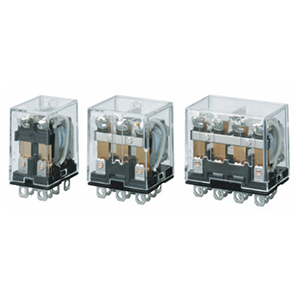
MY2-GS and MY2N-GS
MY4-GS and MY4N-GS
Refer to Common Socket and DIN Track Products for details on Connection Sockets and DIN Track products (sold separately).
Refer to PYF-[][]-PU/P2RF-[][]-PU for details on A Push-In Plus Terminal Block Socket.
PYF08A-E
PYF14A-E

PYF08A-N
PYF14A-N
PYF-08-PU
PYF-14-PU
PY08-02
PY14-02
Hold-down Clips
Front-mounting Sockets
Back-mounting Sockets