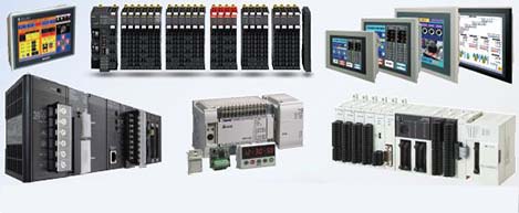
 Automation Systems
 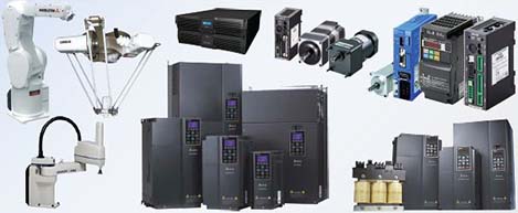 Motion & Power Solutions
 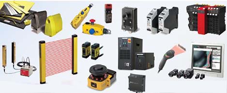 Safety, Vision and IDENT
 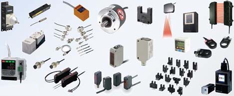 Sensing Solutions
  Control Components
  Switching & Accessories
  Switchgear and Trolley Systems
  Process Weighing
 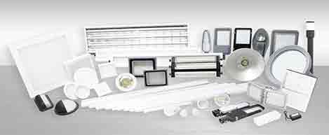 LED Lighting
  Omron
Omron
 Mitsubishi
 Delta
Delta
 Autonics
 Inno
Inno
 Panasonic
 Novotechnik
 Orientalmotor
 Microscan
 IPA
IPA
 Technomech
 Intech
 Honeywell
 IOT & Traceability
 Project & Panel Engg.
 Application Case Studies
 Solutions by Industry
 Solutions by Process
 Solutions by Product
 Youtube Videos
 Corporate Information
 Company Profile
 Quality Policy
 Mission Statement
 Chairman's Message
 Intech Group Companies

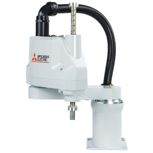
Compact Industrial SCARA
Compact Industrial Robot with light weight space saving arm. Its high speed operation is best suited for pick and place, labelling, tracking
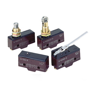

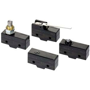
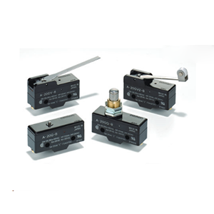
• Incorporates a small permanent magnet in the contact mechanism to deflect the arc to effectively extinguish it.
• Same shape and mounting procedures as the Z Basic Switches.
("-A" is not included in the model numbers.)
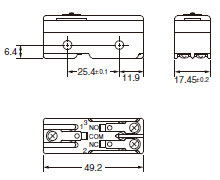
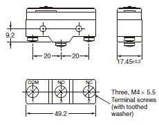
Note: 1. Tighten the terminal screws to a torque of 0.78 to 1.18 Nm.
2. Unless otherwise specified, a tolerance of ±0.4 mm applies to all dimensions.
3. In case of DC voltage, set the COM to the positive terminal.
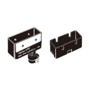
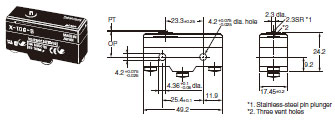
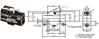
Use M4 mounting screws with plane washers or spring washers to securely mount the Switch. Tighten the screws to a torque of 1.18 to 1.47 Nm.
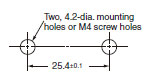
The Switch can be panel mounted, provided that the hexagonal nut of the actuator is tightened to a torque of 2.94 to 4.9 Nm.
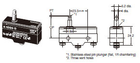
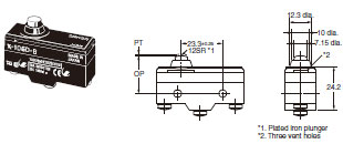
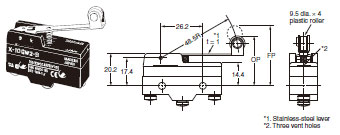
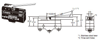
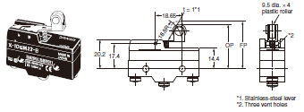
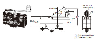
The models, illustrations, and graphics are for screw-terminal models. (The dimensions for models that are omitted here are the same as for pin-plunger models.)
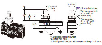
Note: Do not use both the M12 mounting screw and the mounting holes in the case at the same time. Doing so will cause stress to be applied to the Switch, possibly damaging the case or cover.
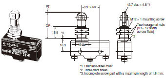
Note: Do not use both the M12 mounting screw and the mounting holes in the case at the same time. Doing so will cause stress to be applied to the Switch, possibly damaging the case or cover.
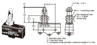
Note: Do not use both the M12 mounting screw and the mounting holes in the case at the same time. Doing so will cause stress to be applied to the Switch, possibly damaging the case or cover.
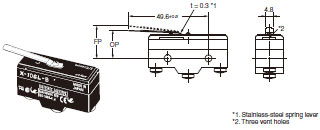
Note: Unless otherwise specified, a tolerance of ±0.4 mm applies to all dimensions.
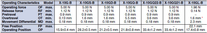
* Be sure to use the switch at the rated OT value of 1.6 mm.
Note: Unless otherwise specified, a tolerance of ±0.4 mm applies to all dimensions.
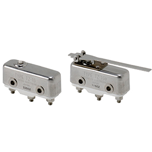
Soldering Terminal Use (Phenol Resin)
Note: The Cover has five thin, easy-to-separate portions for easy lead wire connections.
Screw Terminal Use (Phenol Resin)
Note: The Cover has six thin, easy-to-separate portions for easy lead wire connections.
Soldering Terminal Use (Metal Press Mold)
Note: The Cover has five holes for easy lead wire connections.
Screw Terminal Use (Metal Press Mold)
Note: The Cover has six holes for easy lead wire connections.
Soldering or Screw Terminal Use (Vinyl Chloride)
Note: Each dimension has a tolerance of ±0.4 mm unless otherwise specified. (±0.8 mm for the AP-Z)
Note: 1. Each dimension has a tolerance of ±0.4 mm unless otherwise specified.
2. The material is EAVTC (Epoxide Alkyd Varnished Tetron Cloth) and its heat-resisting temperature is 130°C.
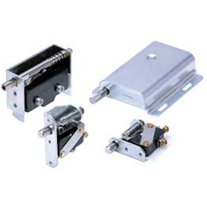
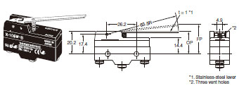
Hinge Lever
XAA-1
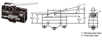
Hinge Roller Lever
ZAA-2
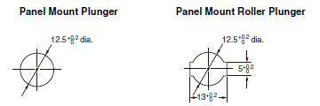
Short Panel Mount Plunger
ZAQ-3
Medium Panel Mount Plunger
ZAQ-2
Long Panel Mount Plunger
ZAQ-1
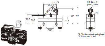
Panel Mount Roller Plunger
ZAQ-22
Note: Each dimension has a tolerance of ±0.4 mm unless otherwise specified.