 Automation Systems
 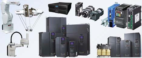 Motion & Power Solutions
  Safety, Vision and IDENT
  Sensing Solutions
  Control Components
  Switching & Accessories
 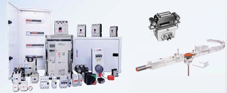 Switchgear and Trolley Systems
 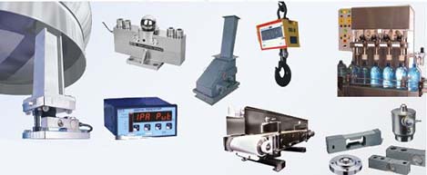 Process Weighing
 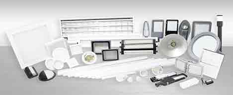 LED Lighting
  Omron
Omron
 Mitsubishi
 Delta
Delta
 Autonics
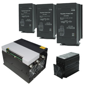
 Inno
Inno
 Panasonic
 Novotechnik
 Orientalmotor
 Microscan
 IPA
IPA
 Technomech
 Intech
 Honeywell
 IOT & Traceability
 Project & Panel Engg.
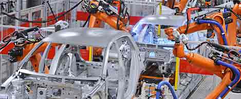
 Application Case Studies
 Solutions by Industry
 Solutions by Process
 Solutions by Product
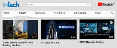 Youtube Videos
 Corporate Information
 Company Profile
 Quality Policy
 Mission Statement
 Chairman's Message
 Intech Group Companies

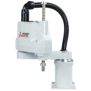
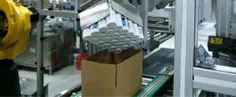
Compact Industrial SCARA
Compact Industrial Robot with light weight space saving arm. Its high speed operation is best suited for pick and place, labelling, tracking

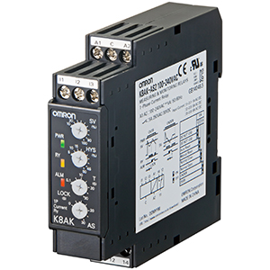
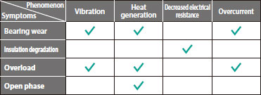
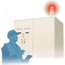
The conventional motor condition check had several check items. Therefore a skilled maintenance engineer was required to judge the motor's maintenance timing. Additionally, inspection was time-consuming because there were many motors.
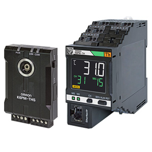
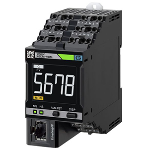
K6CM (comprehensive current diagnosis type) can consistently monitor motor conditions by observing the current waveform of the motor.
Additionally, you can understand the motor's maintenance timing without depending on an engineer, because K6CM provides threshold value setting.
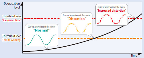
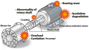
When an abnormality occurs in the load such as rotary shaft or reducer, the motor does not rotate smoothly and a distortion occurs in its current waveform.
K6CM measures its distortion as a degradation level.
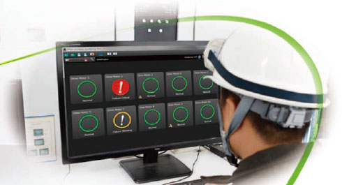
With the accessory software "Motor Condition Monitoring Tool", you can monitor motor conditions remotely.
* The screen is a sample image.

Monitors the 3-phase induction motor which is the driving force of every facility.
last update: March 1, 2018
(Unit: mm)
K6CM-ISZBI52
K6CM-CICB400
K6CM-CICB600
The cable supplied with the CT is shipped in the connected state.
last update: March 1, 2018