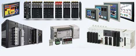
 Automation Systems
 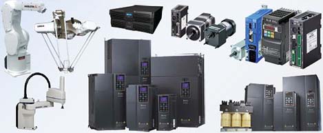 Motion & Power Solutions
 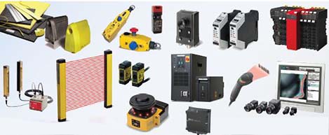 Safety, Vision and IDENT
 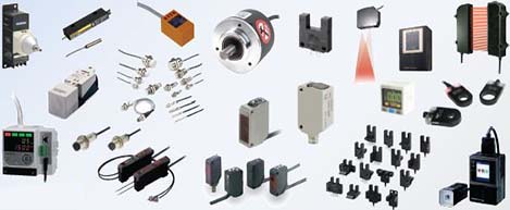 Sensing Solutions
 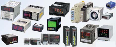 Control Components
 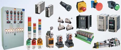 Switching & Accessories
 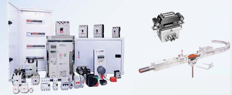 Switchgear and Trolley Systems
 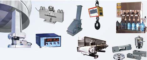 Process Weighing
 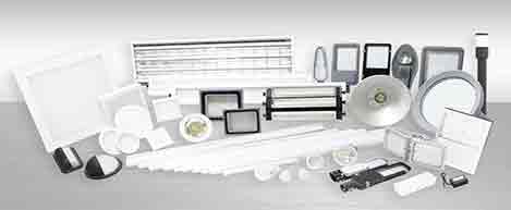 LED Lighting
  Omron
Omron
 Mitsubishi
 Delta
Delta
 Autonics
 Inno
Inno
 Panasonic
 Novotechnik
 Orientalmotor
 Microscan
 IPA
IPA
 Technomech
 Intech
 Honeywell
 IOT & Traceability
 Project & Panel Engg.
 Application Case Studies
 Solutions by Industry
 Solutions by Process
 Solutions by Product
 Youtube Videos
 Corporate Information
 Company Profile
 Quality Policy
 Mission Statement
 Chairman's Message
 Intech Group Companies

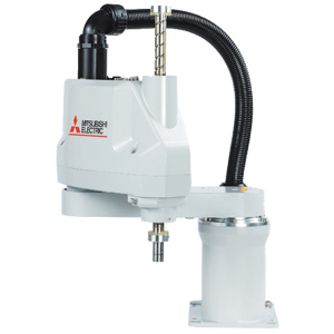
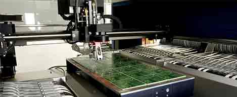
Compact Industrial SCARA
Compact Industrial Robot with light weight space saving arm. Its high speed operation is best suited for pick and place, labelling, tracking
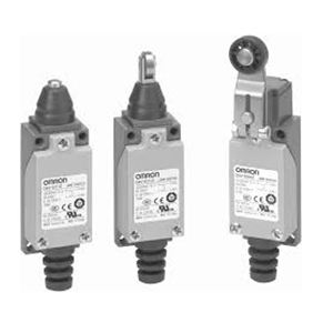

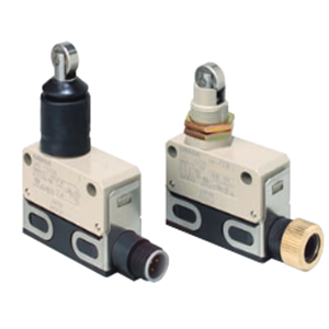
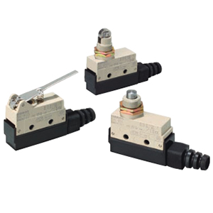
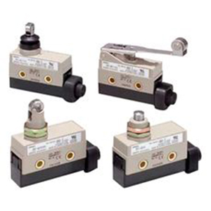
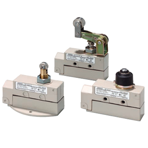
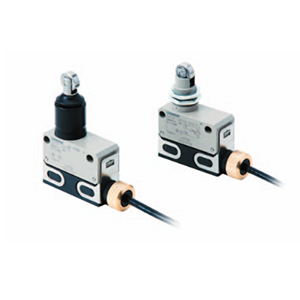
• Compact new design approximately 1/3 the size of OMRON vertical Limit Switches.
• Structure enables the terminal section to be fully opened for easy wiring.
• RoHS complaint.
• Degree of protection: IP65
Roller Lever
D4V-8104Z
Rod Lever
D4V-8107Z
Adjustable Roller Lever
D4V-8108Z
Push Plunger
D4V-8111Z
Roller Plunger
D4V-8112Z
Crossroller Plunger
D4V-8122Z
Coil Spring
D4V-8166Z
Wire Spring
D4V-8169Z
Note: Unless otherwise specified, the tolerances are ±0.4 mm for the above dimensions for each model.